A. Loading diagram and design data
External loading diagram
|
Loading diagram of element 5 |
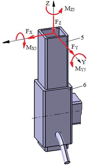 | |
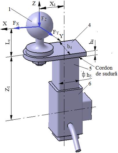
Design data External forces: FX, FY, FZ act at distances Lc + h4 (Ex.3.1, Ex.3.2) and X1 (Ex.1.2.2); the moments at the centre of the square section (the welded joint) are calculated (Calc.0): MX5 = FY (Lc + h4), MY5 = FX (Lc + h4) + FZ X1, MZ5 = FY X1. Dimensional constraints: a square tube semi-finished product is used, welded to tie rod 4 of width b4 and thickness h4 (Ex.3.2); so that a continuous fillet weld can be applied, the side of the square tube (h5) must be smaller than the width b4 (h5 < b4); the length of element 5 is determined taking dimension Z1 into account (Ex.1.2.2). Operating constraints: temperature T = (−30…40) °C; outdoor working environment with high humidity. Design constraints: weldable material. | |
B. Choice of material and heat treatment
Since the upper column (element 5) is a welded part, a weldable steel is adopted (e.g. S185, S235, S275) (Annex.M.01), according to SR EN 10025-2 (STAS 500/2). These steels are not heat-treated before welding; after welding, the subassembly may undergo stress-relief annealing. For the adopted steel, the yield strength σ02 and the ultimate tensile strength σr are retained for the calculations.
C. Design of the constructive shape
Constructive model
Constructive features and constraints
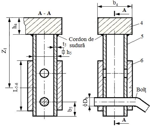
– for constructive reasons and minimum weight, a square tube semi-finished product is adopted;
– element 4 is joined to element 5 by a fillet weld, and the size of the square tube must allow a continuous weld bead (h5 < b4).
Notes.
– dimension L5-6 results from the design of joint 5-6 (tube-in-tube joint; Sec.4.1, Ex.4.1);
– the pin hole diameter Db is determined from the pin joint calculation (Sec.4.2, Ex.4.2).
D. Calculation model, sizing and checking
Calculation model
Calculation assumptions and loads
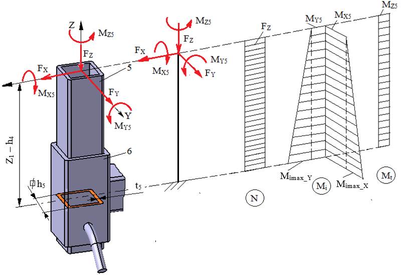
– the loads are transmitted from element 5 to element 6 by direct contact, and for sizing purposes element 5 is considered fixed at the centre of body 6;
– the calculation model of element 5 is a straight cantilever bar of square hollow section with side h5 and wall thickness t5, loaded in compression by FZ, in bending by FX, FY, MX5 and MY5, in torsion by MZ5 and in shear by FX and FY;
– the effect of the pin holes is neglected;
– since a sizing model accounting for all loads is quite complex, a simplified model is adopted, which considers the main oblique bending load given by the forces FX, FY and the moments MX5, MY5;
– once the dimensions have been obtained from the simplified model and the tube-in-tube joint has been calculated (Sec.4.1, Ex.4.1), the element is checked with the MDESIGN package (Guide.4.5, Ex.4.5) and by FEA (ANSYS) (Guide.4.6, Ex.4.6).
Calculation data
– loads: the forces FX, FY and the moments MX5, MY5;
– shape and dimensions: square hollow tube; the thickness/side ratio is taken as k = t/h = 0.05…0.15;
– material: σ02 – the yield strength; c = 2…3 – the safety factor; σat = σ02/c – the allowable tensile stress; σaî = (1.05…1.1)σat – the allowable bending stress.
Calculation relations
– maximum bending moments in the critical section (simplified model),
Mî max_Y = MY5 + FX (Z1 – h4); Mî max_X = MX5 + FY (Z1 – h4). (Calc.0)
– bending strength condition in the critical section (at the corner of the square section),
σmax = 
 +
+  =
= 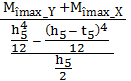 ≤ σaî.
– sizing: from the last part of the relation above, and since for square tubes usually t = k h (k = 0.05…0.15), the required tube size is
 =
= 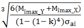 (Calc.3.4.1)
and then  = k ; a square hollow tube with standard dimensions h5 ≥ and t5 ≥ is chosen from Annex.ST.02.
E. Design of the constructive-technological shape
Constructive-technological drawing
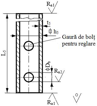
Recommendations for choosing the dimensions and technological parameters
– dimensions: h5, t5; the other dimensions result from the design of joint 5-6 (Sec.4.1, Ex.4.1) and of the pin joint (Sec.4.2, Ex.4.2);
– technological operations: milling the end portions and drilling the pin holes; the other surfaces remain unmachined, as indicated by the attached symbol;
– roughness of the machined surfaces: Ra1 = 6.3 µm or Ra1 = 12.5 µm; Ra2 = 3.2 µm or Ra2 = 6.3 µm;
– the position of the pin hole (and, if needed, of the adjustment hole) is set when drawing the assembly.