Design data
External forces: FX = 1500 N, FY = 300 N and FZ = 700 N act at distance Lc = 70 mm; the moments at the centre of the clearance hole are:
MX4 = FY Lc = 21000 Nmm,
MY4 = FX Lc = 105000 Nmm.
Dimensional constraints: X1 = 80 mm.
Operating constraints: temperature T = (−30…40) °C; outdoor working environment with high humidity.
Design constraints: weldable material.
Material and heat treatment
Since the tie rod is a welded part, S235 steel according to SR EN 10025-2 (STAS 500/2) is adopted.
Material properties
| Material | Heat treatment | Hardness [HB] | Yield strength | Ultimate tensile strength |
|---|---|---|---|---|
| S235 | – | – | σ02 = 235 MPa | σr = 400 MPa |
Sizing
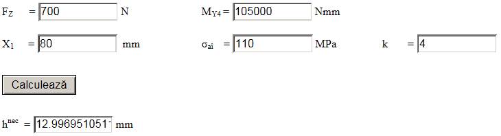
From the bending strength condition of the associated bar, with FZ = 700 N, MY4 = 105000 Nmm, X1 = 80 mm, σaî = (1.05…1.1)σ02/c = (82.25…129.2) MPa (σaî = 110 MPa is adopted) and k = 4, the thickness hnec = 13 mm and the width bnec = 52 mm result; a flat bar semi-finished product with standard dimensions b4 = 60 mm and h4 = 15 mm is adopted.
Constructive-technological shape
Constructive-technological drawing
|
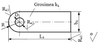
Recommendations for choosing the dimensions and technological parameters – dimensions: b4 = 60 mm, h4 = 15 mm, R = 30 mm, L4 = 110 mm; the hole diameter D1 is determined when designing joint 1-4; – protective chamfers of 0.5×45° are adopted on sharp edges; – machining involves milling the end portions and drilling; the other surfaces remain unmachined, as indicated by the attached symbol; – roughness of the machined surfaces: Ra1 = 12.5 µm, Ra2 = 6.3 µm. |