A. Loading diagram and design data
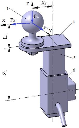
External loading diagram
|
Loading diagram of joint 5-6 |
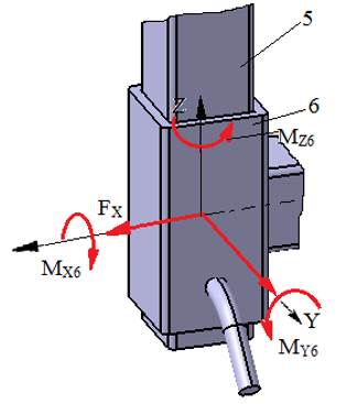 | |
Design data External forces: FX, FY, FZ act at distances Lc (Ex.3.1), X1, Z1 (Ex.1.2.2); the moments at the centre of the joint section (tube-in-tube) are calculated (Calc.0): MX6 = FY (Lc + Z1), MY6 = FX (Lc + Z1) + FZ X1, MZ6 = FY X1. Dimensional constraints: the square tube 5, of size h5 and wall thickness t5 (Ex.3.4), is assembled with the square tube 6, of size h6 and wall thickness t6. Operating constraints: temperature T = (−30…40) °C; outdoor working environment with high humidity. Design constraints: tube 5 is inserted into tube 6, with loose clearance fits on the sides of the inner and outer squares. | |
B. Choice of materials and heat treatments
Since elements 5 and 6 are welded to other elements, weldable steels are adopted. For the adopted steels, the yield strength σ02 and the ultimate tensile strength σr are retained for the calculations. For conforming steel-on-steel contacts, the allowable crushing stress is σas = (60…90) MPa.
C. Design of the constructive shape
Constructive model
Constructive features and constraints
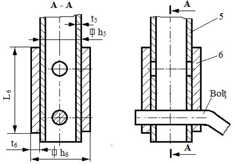
For correct operation, conforming contacts (over large surfaces) are required between tubes 5 and 6; they are obtained by a clearance fit, ensured by the tube dimensions.
D. Calculation model, sizing and checking
Calculation model
|
Transmission of the moment MZ
|
| a | b |
Transmission of the force FX and the moment MY
|
Transmission of the force FY and the moment MX
|
| c | d |
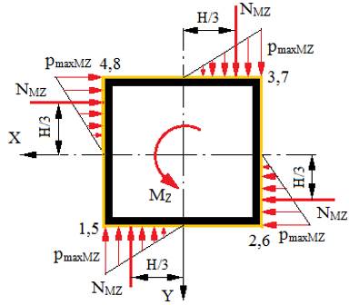
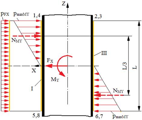
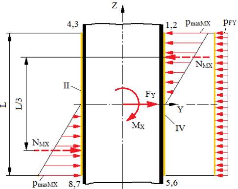
Calculation assumptions and loads
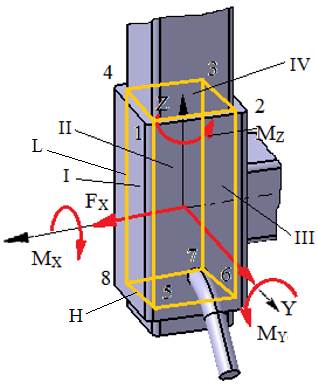
– the forces FX, FY and the moments MX and MY are transmitted from tube 5 to tube 6 by direct contact between the two tubes fitted with clearance (linear distribution of the contact pressures) over the rectangular surfaces I, II, III and IV;
– the force FZ is transmitted from tube 5 to tube 6 by a pin with a clearance fit in tube 5 and a light interference fit in tube 6; the pin holes are not considered in the tube-in-tube calculation;
– the moment MZ generates linearly distributed pressures on the contact surfaces I, II, III and IV, with maximum pmaxMZ;
– the forces FX and FY generate uniformly distributed crushing pressures pFX and pFY on the contact surfaces I and II, respectively;
– the moments MX and MY generate linearly distributed crushing pressures on the contact surfaces I, III and II, IV, with maxima pmaxMX and pmaxMY, respectively.
Known data
– loads: FX, FY, MX = MX6, MY = MY6, MZ = MZ6;
– shapes and dimensions: the size of the square bore H = h5; the wall thickness of the inner tube t5 and of the outer tube t6; the length L is unknown (to be determined);
– materials: σas = 60…90 MPa – the allowable crushing stress.
Calculation relations
Contact pressures
– the contact pressures on surfaces I and II generated by the forces FX and FY respectively (figs. c, d) are:
pFX =  =
= 
and, respectively,
pFY = = .
– the maximum contact pressures on surfaces I, III and II, IV generated by the moments MY and MX respectively (figs. c, d) are:
pmaxMY = 2 = 2  = 2
= 2 =
= 
and, respectively,
pmaxMX = 2 = 2  = 2
= 2 =
= 
– the maximum contact pressure on surfaces I, II, III, IV generated by the moment MZ (fig. b),
pmaxMZ = 2 = 2  = 2
= 2  =
=  .
.
Crushing strength condition of the tube-in-tube joint
The maximum contact pressures, obtained by adding the pressures generated by the loads, are limited to the allowable crushing stress of the materials in contact,
σmax = max(pmax4/I + pmax1/II) = max(pFX + pmaxMY + pmaxMZ, pFY + pmaxMX + pmaxMZ) =
= max( + + ,  + + ) ≤ σas.
Sizing
From the relation above, with H known, the following equations are obtained:
σas H2 L2 – (FX H + 3 MZ) L − 12 H MY = 0,
σas H2 L2 – (FY H + 3 MZ) L − 12 H MX = 0,
which, after substituting the known parameters and solving (Calc.4.1.1), usually give two positive solutions.
Finally, L6 is taken as the largest of the positive values of L (a larger whole value is adopted).
Choosing the tube section dimensions
Since the section of tube 5 has been determined by calculation (Ex.3.4), the dimensions of tube 6 can be taken from Annex.ST.02 with larger values, observing the constraints t6 ≥ t5, h6 = h5 + 2 t6.
E. Design of the constructive-technological shape
Constructive-technological drawings
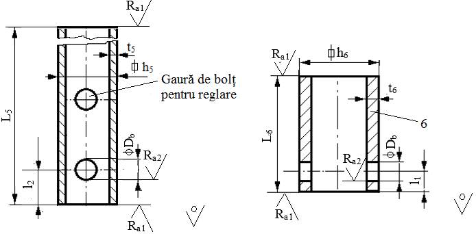
Recommendations for choosing the dimensions and constructive-technological parameters:
– dimensions: h5, t5; h6, t6, L6, Db, L5 = Z1 – h4 + L6/2 + 2Db, l1 = 1.5Db; l2 = 2Db; the bore diameter Db is determined from the pin joint calculation (Sec.4.2, Ex.4.2);
– technological operations: milling the tube ends, drilling/reaming the pin holes;
– roughness of the machined surfaces: Ra1 = 6.3 µm or Ra1 = 12.5 µm; Ra2 = 6.3 µm or Ra2 = 3.2 µm;
– sharp edges are chamfered 1×45°;
– the position of the pin hole (and, if needed, of the adjustment pin hole) is set when drawing the assembly.