A. Loading diagram and design data
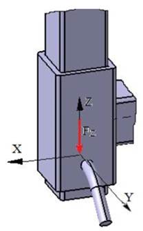
External loading diagram
|
Loading diagram of the pin joint |
 |
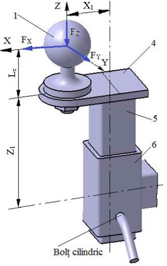
Design data
External forces: FZ.
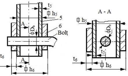
Dimensional constraints: the square tube 5, of size h5 and thickness t5, is assembled with the square tube 6, of size h6 and thickness t6 (Ex.4.1); Z1 (Ex.1.2.2).
Operating constraints: temperature T = (−30…40) °C; outdoor working environment with high humidity.
Design constraints: dimensional interchangeability.
B. Choice of materials and heat treatments
Elements 5 and 6 are made of weldable steel (Ex.4.1).
The pin is made of steel for mechanical construction (Annex.M.01), e.g. E295, E335, E360 (SR EN 10025/2005), or even of a quenching-and-tempering steel C35, C40, C45.
For each material identify the yield strength σ02 and the ultimate tensile strength σr. The allowable shear stress of the pin material is τaf = (0.6…0.8)σat, with σat = σ02/c and the safety factor c = 2…3; the allowable steel-on-steel crushing stress is σas = (60…90) MPa (lower values are adopted for mild steels).
C. Design of the constructive shape
Constructive model
|
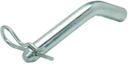
Constructive features and constraints: – a headed pin with a 45° head and a split-pin hole is adopted (Annex.ST.09); – the pin passes through both walls of the tubes; – for interchangeability, a standard pin diameter Db is adopted.
|
D. Calculation model, sizing and checking
General calculation model
|
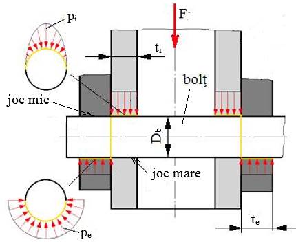
Calculation assumptions and loads The force F is transmitted by shape (direct contact) from the inner tube to the pin over two semi-cylindrical surfaces on which, because of the larger clearance, crushing pressures with a cosine distribution and maximum pi are assumed; the force F is then transmitted by shape (direct contact) from the pin to the outer tube, also over two semi-cylindrical surfaces on which, because of the small clearance, uniformly distributed crushing pressures with maximum pe are assumed. Calculation data – loading: F = FZ (the transverse force on the pin); – geometry: ti = t5, te = t6 (wall thicknesses of the assembled tubes); – materials: σ02 – the yield strength of the tube material; σas – the allowable crushing stress for steel-on-steel contacts; τaf – the allowable shear stress of the pin material. |
Calculation relations
Crushing strength condition of the pin joint
The maximum contact pressures on the pin surfaces are limited to the allowable crushing stress of the materials in contact,
σmax = max(pi, pe) = max 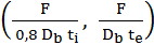
 = min (σasb, σasț),
where σasb is the allowable crushing stress of the pin material and σasț that of the tube material.
Sizing
From the relation above, the required pin diameter is
 = max
= max 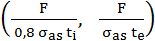 , (Calc.4.2.1)
where F = FZ, ti = t5, te = t6, and σas is the allowable crushing stress of the tube material.
Db > is adopted (Annex.ST.09); for technological and handling reasons Db ≥ 8 mm is recommended.
Checking the pin in shear
The actual shear stress is
τf =  =
=  =
=  .
.
The check is
≤ τaf. (Calc.4.2.2)
E. Design of the constructive-technological shapes
Constructive-technological drawings
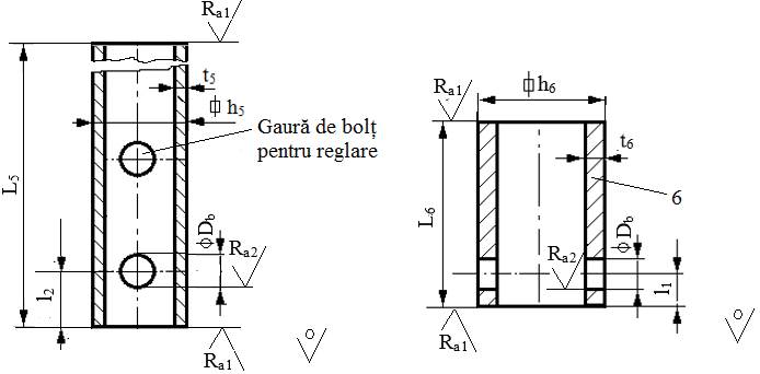
Recommendations for choosing the dimensions and constructive-technological parameters:
– dimensions: h5, t5; h6, t6, L6; Db, l1 = 1.5Db; l2 = 2Db; L5 = Z1 – h4 + L6/2 − l1 + l2;
– technological operations: milling the tube ends, drilling/reaming the pin holes;
– roughness of the machined surfaces: Ra1 = 6.3 µm or Ra1 = 12.5 µm; Ra2 = 6.3 µm or Ra2 = 3.2 µm;
– sharp edges are chamfered 1×45°;
– the position of the pin hole (and, if needed, of the adjustment pin hole) is set when drawing the assembly.
Recommendations for choosing the joint components
– split pin (Annex.ST.10);
– washer for pins (Annex.ST.11).