A. Loading diagram and design data
External loading diagram
|
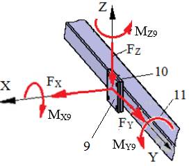
Loading diagram of joint 9-10 |
 |
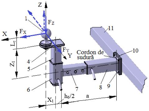
Design data
External forces: FX, FY, FZ act at distances Lc (Ex.3.1), X1, Z1 (Ex.1.2.2), h6 (Ex.4.1) and a (Ex.5.1); the moments at the centre of flange 9 are calculated (Calc.0):
MX9 = FY (Lc + Z1),
MY9 = FX (Lc + Z1) + FZ (X1 + h6/2 + a),
MZ9 = FY (X1 + h6/2 + a).
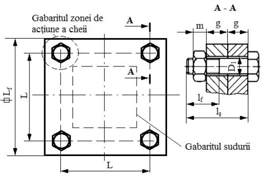
Dimensional constraints: flanges 9 and 10, of thickness g (Ex.4.3), are connected by 4 bolted joints; the flange dimensions are chosen so as to give access to the wrenches used to tighten the standard bolts and nuts.
Operating constraints: temperature T = (−30…40) °C; outdoor working environment with high humidity.
Design constraints: the flange materials must be weldable; the bolt and nut materials are chosen according to the relevant regulations.
B. Choice of materials and heat treatments
Since elements 9 and 10 are welded parts, a weldable steel is adopted (e.g. S185, S235, S275; Annex.M.01), according to SR EN 10025-2 (STAS 500/2).
The steels of the standard fasteners (bolts and nuts) can be chosen from property classes 6.6, 6.8, 8.6, 8.8. These steels are not heat-treated by the user; for the adopted class, the yield strength σ02 and the ultimate tensile strength σr are retained for the calculations, determined from the class symbol (e.g. for class 6.8, σ02 ≈ 6·8·10 = 480 MPa and σr ≈ 6·100 = 600 MPa).
C. Design of the constructive shape
Constructive drawing
|
Constructive features and constraints – for flanges 9 and 10, a flat bar semi-finished product with thickness g = {10, 12} mm is adopted (Ex.4.3, Annex.ST.01); – the dimensions of flanges 9 and 10 are set from overall-size considerations, so that elements 8 and 11 can be welded in the central zone and the bolt–nut joints can be tightened with an open-end or socket wrench; note that the lower tie rod body is welded to flange 9 (weld envelope h8 + 2a, Ex.4.3) and the central bar 11 to flange 10 (weld envelope h11 + 2a, Ex.6.1); taking into account the space needed by the wrench, the side of the square flanges Lf is adopted; in practice, for M10, M12, M14 bolts one can take Lf = max(h8, h11) + 2a + 60…80 mm (a being the throat thickness of weld 8-9); – the bolt clearance holes, of diameter D1, are placed at the corners of a square of side L = (Lf + h8 + 2a)/2. |
D. Calculation model, sizing and checking
Calculation model
Calculation assumptions and loads
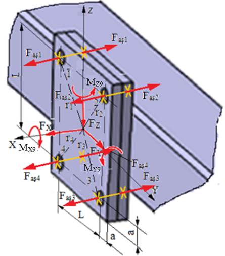
– the loads are transmitted from flange 9 to flange 10 partly through the shanks of the four bolts and their threads and partly by friction between the two flanges; for sizing, the most heavily loaded bolt must be identified, using the superposition principle;
– the force FX loads the joint axially and centrically; the moments MZ9 and MY9 load it axially and eccentrically; the forces FY, FZ and the moment MX9 load it transversely and centrically (they are transmitted by friction);
– the bolts are fitted with clearance, and their shanks are mainly loaded in tension;
– the most heavily loaded bolt is sized from the tensile strength condition of its shank.
Calculation data
– loading: FX, FY, FZ; MX9, MY9, MZ9;
– shapes and dimensions: square flange of size Lf (see step C); side L of the hole-pattern square (see step C); a = (Lf – L)/2; r1 = r2 = r3 = r4 = r =  L/2;
L/2;
– material: property class m.n (possible classes: 6.6, 6.8, 8.6, 8.8), σ02 = m·n·10 MPa – the yield strength; c = 2…3 – the safety factor; σat = σ02/c – the allowable tensile stress;
– friction parameters: µ = 0.15…0.25 – the sliding friction coefficient between the thread flanks; µ1 = 0.15…0.25 – the sliding friction coefficient between flanges 9 and 10; µ2 = 0.15…0.25 – the sliding friction coefficient between nut and washer.
Calculation relations
Finding the most heavily loaded bolt
Axial forces in the bolts due to each load:
– bolt forces due to the force FX, which loads the joint axially and centrically,
 =
=  =
=  =
=  =
=  , (Calc.0)
– bolt forces due to the moment MZ9, which loads the joint axially and eccentrically,
 =
=  =
= 
 ,
,  =
=  =
=  ; (Calc.6.5.1)
– bolt forces due to the moment MY9, which loads the joint axially and eccentrically,
 =
=  =
=  ,
,  =
=  = ; (Calc.6.5.2)
– bolt forces due to the resultant of FY and FZ, which loads the joint transversely and centrically,
 =
=  =
=  =
=  =
=  , (Calc.6.5.3)
where βa = 1.2…1.4 is the safety factor against slipping and µ1 = 0.15…0.25 the sliding friction coefficient between flanges 9 and 10;
– bolt forces due to the moment MX9, which loads the joint transversely and centrically,
 =
=  =
=  =
=  =
= 
 , (Calc.6.5.4)
where r is the half-diagonal of the square on which the bolt axes lie (r1 = r2 = r3 = r4 = r = L/2).
Total axial forces in the bolts,
Faș1 = + + + + , (Calc.0)
Faș2 = + + + + , (Calc.0)
Faș3 = + + + + , (Calc.0)
Faș4 = + + + + . (Calc.0)
The maximum value Faș = max(Faș1, Faș2, Faș3, Faș4) identifies the most heavily loaded bolt, which is sized by the strength calculation.
Axial tightening (preload) force in the bolts at assembly
Fst = max( + , + , + , + ). (Calc.0)
Note. This force provides the clamping between flanges 9 and 10 needed for friction without slipping.
Sizing the threaded shank
– from the tensile strength condition of the most heavily loaded bolt, the required minor thread diameter is
 =
=  , (Calc.3.3.2)
where β = 1.1…1.3 is a correction factor for the torsion that arises when the joint is tightened, and σat the allowable tensile stress.
– choice of the standard dimensions: from Annex.ST.03, the thread parameters d1 (d1 ≥ ), d2, d (Md), p; matched to the thread size (Md), the clearance hole diameter D1 (medium series) is taken from Annex.ST.05.
Tightening moments of the joint
– screwing moment (thread friction),
Mî = Fst  tg(arctg
 + arctg
 ), (Calc.3.3.4)
where µ = 0.15…0.25 is the friction coefficient in the thread, α = 60° the profile angle of the metric thread and p the thread pitch;
– pivoting friction moment between nut and washer,
Mp = Fst  μ2
μ2 , (Calc.3.3.5)
where µ2 = 0.15…0.25 is the friction coefficient between nut and washer and D1 the clearance hole diameter;
– nut tightening (wrench) torque,
Mc = Mî + Mp. (Calc.0)
Checks
– checking the threaded bolt shank under combined loading (tension and torsion) at tightening, with
σe ≤ σat,
where the equivalent stress is
σe = 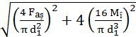 . (Calc.3.3.6)
– checking the self-locking condition,
β2 ≤ φ′,
where
β2 = arctg, φ′ = arctg, (Calc.3.3.7)
and φ′ is the reduced friction angle.
Notes.
– the strength calculation considers the most unfavourable case, with all external forces acting, to avoid unloading the joint and thus losing the ability to transmit FY, FZ and MX9 by friction;
– since a nut with a standard thread was adopted, no strength calculation of its thread is needed: the nut design already accounts for it;
– for metric threads, the self-locking condition usually does not need checking, as it is ensured by design.
E. Design of the constructive-technological shape
Constructive-technological drawing
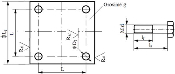
Recommendations for choosing the dimensions and constructive-technological parameters:
– dimensions: Lf, L, g, D1;
– roughness of the surfaces machined by milling and drilling: Ra1 = 6.3 µm or Ra1 = 12.5 µm; Ra2 = 6.3 µm or Ra2 = 12.5 µm;
– sharp edges are chamfered 1×45°.
Recommendations for choosing the fastener dimensions:
– hexagon head bolt (Annex.ST.12): Md, d, S, D, k, l, lf, lș;
– hexagon nut (Annex.ST.04): Md, S, m;
– flat washer (Annex.ST.06): d, d1, d2, h;
– Grower spring washer (Annex.ST.07): MN d, d1, d2, g.