Design data
External forces: FX = 1500 N, FY = 300 N, FZ = 700 N act at distances Lc = 70 mm, X1 = 80 mm, Z1 = 180 mm, h6 = 60 mm, h7 = 50 mm, h8 = 60 mm, a = 140 mm, b = 55 mm; the moments at the centre of the joint are:
MX8 = FY (Lc + Z1) = 75000 Nmm,
MZ8 = FY (X1 + h6/2 + b + h8/2) = 58500 Nmm,
MY8 = FX (Lc + Z1) + FZ (X1 + h6/2 + b + h8/2) = 511500 Nmm.
Dimensional constraints: the square tubes 7 and 8, with sides h7 = 50 mm, h8 = 60 mm and wall thicknesses t7 = 5 mm, t8 = 5 mm, are assembled together.
Operating constraints: temperature T = (−30…40) °C; outdoor working environment with high humidity.
Design constraints: tube 7 is inserted into tube 8, with loose clearance fits on the sides of the outer and inner squares.
Materials and heat treatments
Weldable S235 steel according to SR EN 10025-2 (STAS 500/2) was adopted for elements 7 and 8.
Material properties
| Material | Heat treatment | Hardness [HB] | Yield strength | Ultimate tensile strength |
|---|---|---|---|---|
| S235 | – | – | σ02 = 235 MPa | σr = 360 MPa |
Since all the materials in contact are steels, the allowable crushing stress is taken as σas = 70 MPa.
Sizing
From the sizing relations obtained from the crushing strength conditions of the tube-in-tube joint, with FX = FZ = 700 N, FY = 300 N, MX = MZ8 = 58500 Nmm, MY = 515500 Nmm, MZ = MX8 = 75000 Nmm and σas = 70 MPa, the following solutions result:
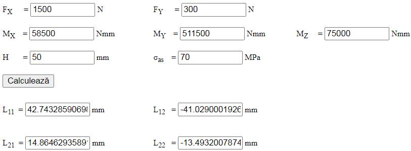
The length of the tube-in-tube joint 7-8 is therefore L = max (42.74; 14.86) = 42.74 mm; L7-8 = 60 mm is adopted (a larger value was chosen to leave extra room for the pin joint).
Constructive-technological shape
Constructive-technological drawings
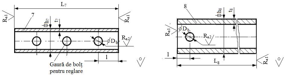
Adopted constructive-technological parameters
– dimensions: h7 = 50 mm, t7 = 5 mm, h8 = 60 mm, t8 = 5 mm, L7 = 105 mm, L8 = 95 mm, l = 30 mm; the pin bore diameter Db is determined from the pin joint calculation;
– technological operations: milling the tube ends, drilling/reaming the pin holes;
– roughness of the machined surfaces: Ra1 = 12.5 µm; Ra2 = 6.3 µm;
– sharp edges are chamfered 1×45°;
– the position of the pin hole (and, if needed, of the adjustment pin hole) is set when drawing the assembly.