1. Input data and results
Geometry data
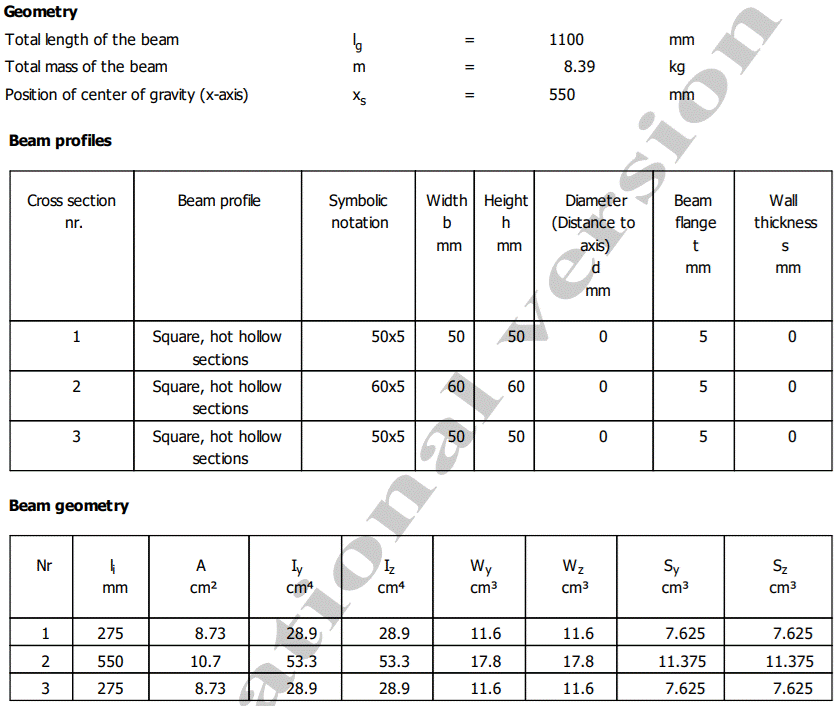
Meaning
lg – total length of the beam; m – total mass of the beam; xs – position of the centre of gravity on the X axis; Iy – moment of inertia about the y axis; Iz – moment of inertia about the z axis; Wt – torsional section modulus; Wy – section modulus about the y axis; Wz – section modulus about the z axis; Sy – first moment of area about the y axis; Sz – first moment of area about the z axis.
Loading data
Axial-force loading

Radial-force loading

Bending-moment loading

Torsional-moment loading

Material data
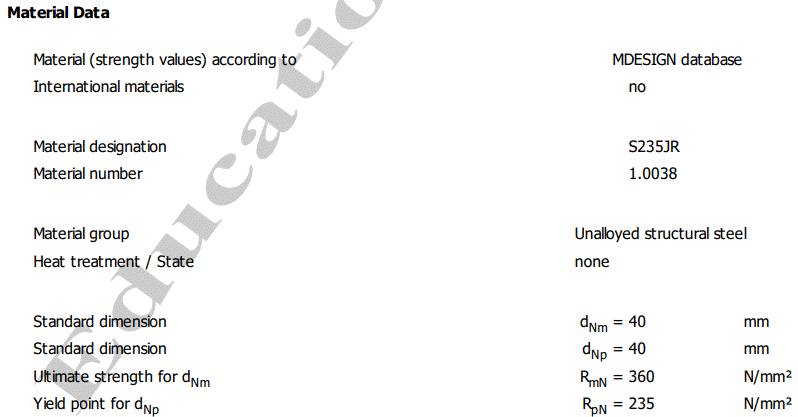
Meaning
RpN – yield strength; RmN – ultimate tensile strength.
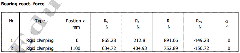
Support reactions
Bending moment diagrams
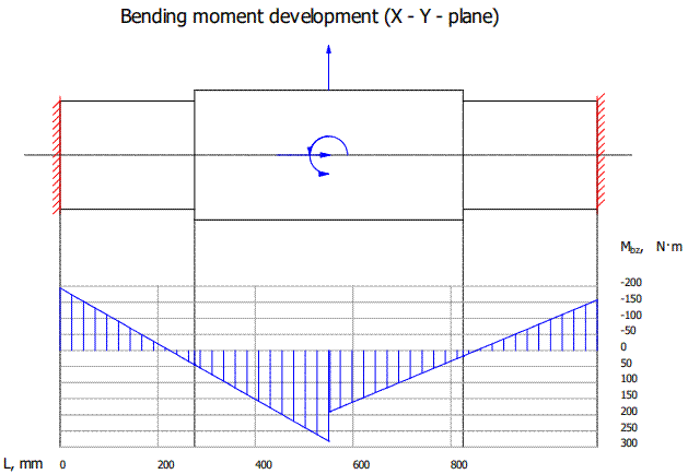
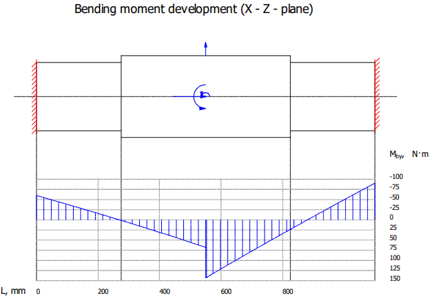
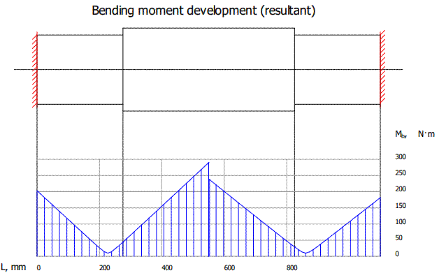
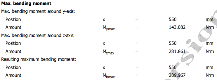
Meaning
Mbz – bending moment development in the X–Y plane; Mby – bending moment development in the X–Z plane; Mb – resultant bending moment development.
Stress values and diagrams
Maximum normal stresses: values and diagrams
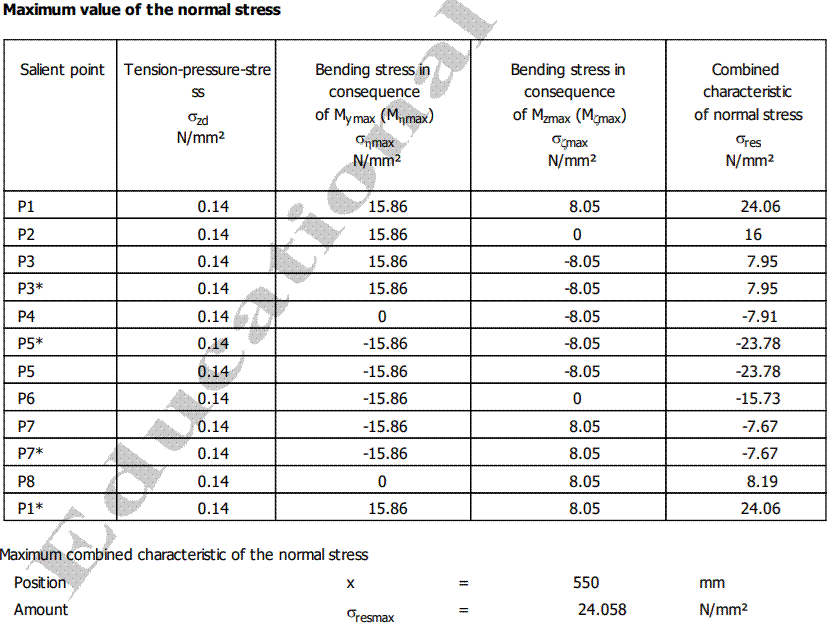
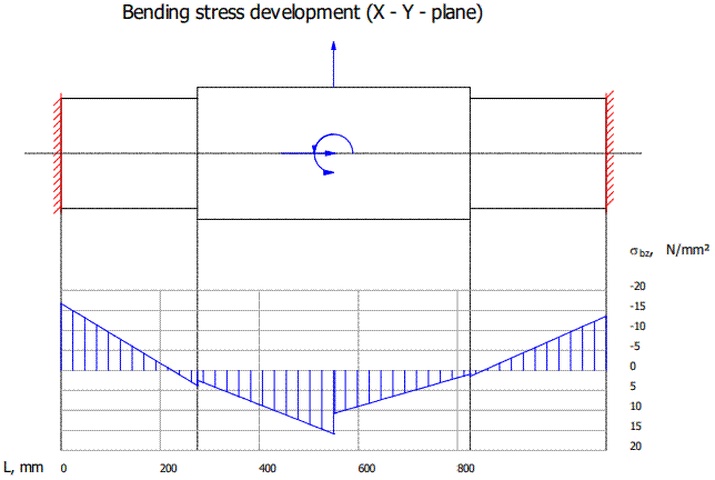
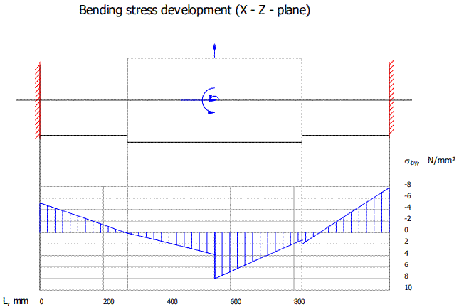
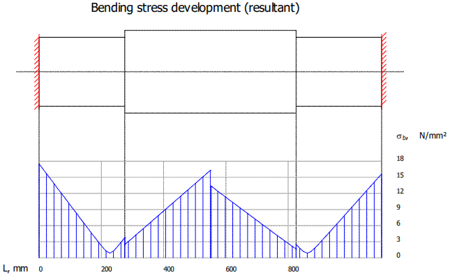
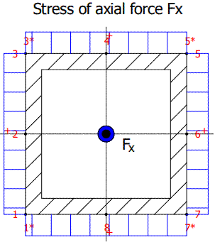
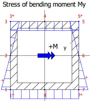
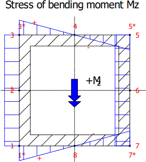
Meaning
Salient point – representative points P1, P2, P3, P3*, P4, P5, P5*, P6, P7, P7*, P8, P1* of the cross-section; σzd – tension-pressure (tensile/compressive) stress; σηmax – bending stress due to Mymax; σζmax – bending stress due to Mzmax; σres – combined (resultant) normal stress; σbz – bending stress development in the X–Y plane; σby – bending stress development in the X–Z plane; σb – resultant bending stress development; Stress of axial force Fx – axial stress due to Fx; Stress of bending moment My – stress due to My; Stress of bending moment Mz – stress due to Mz.
Maximum shear stresses: values and diagrams
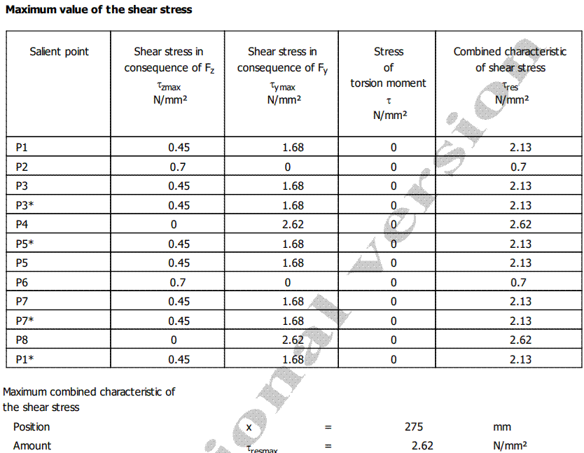
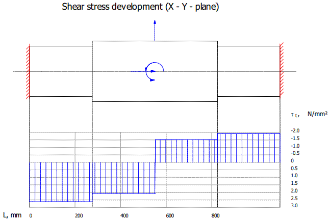
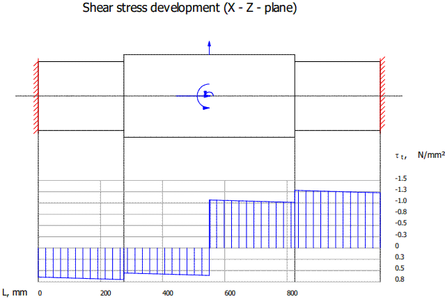
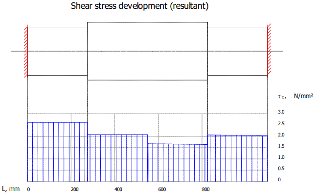
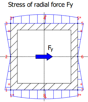
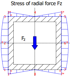
Meaning
Salient point – representative points P1, P2, P3, P3*, P4, P5, P5*, P6, P7, P7*, P8, P1* of the cross-section; τzmax – shear stress due to Fzmax; τymax – shear stress due to Fymax; τres – combined (resultant) shear stress; τ – shear stress due to the torsional moment T.
Equivalent stress and safety factor: values and diagrams
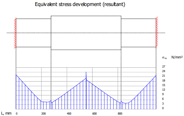
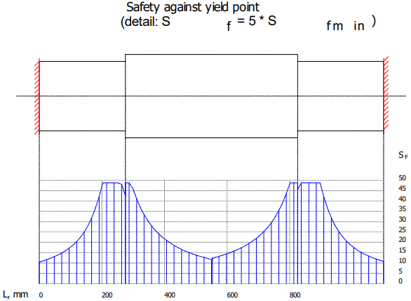
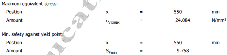
Meaning
σvx – equivalent stress development (resultant); σvxmax – maximum equivalent stress; SF – safety against the yield point; SFmin – minimum safety factor against yielding.
Transverse displacements (deflections) and rotations: values and diagrams
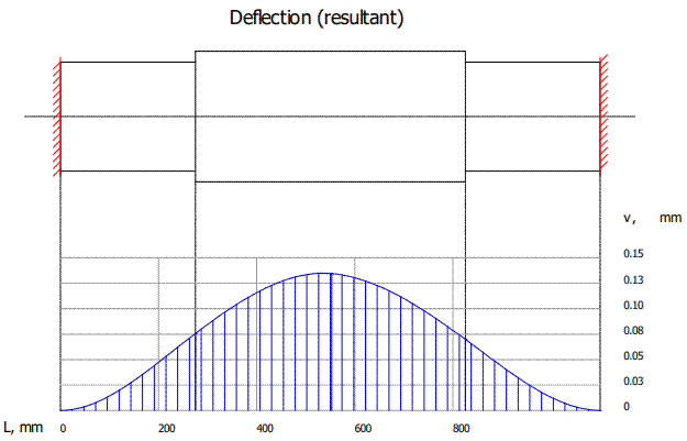
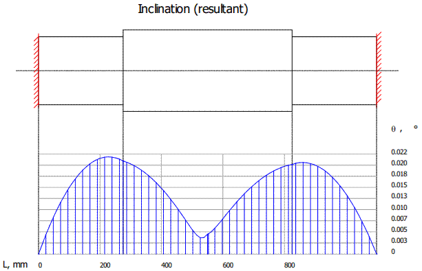
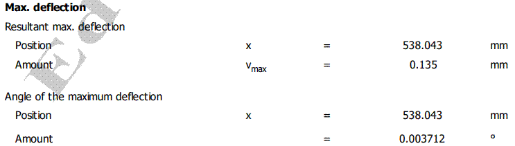
Meaning
v – resultant transverse deflection; θ – resultant inclination (rotation); vmax – maximum resultant deflection; θmax – maximum rotation (angle of the maximum deflection).
2. Checks
Check under combined loading
The check under combined loading aims to prevent permanent plastic deformation of the bar, based either on stresses,
σvxmax ≤ σa,
or on safety factors,
c ≥ ca,
where σvxmax is the maximum equivalent stress, σa = σ02/ca the allowable stress against yielding (plastic deformation), σ02 the yield strength and ca the allowable (minimum) safety factor, which may be taken as ca = 1.5…2.5; c = σ02/σvmax is the minimum safety factor.
Applying the combined-loading check
σvxmax ≤ σa; 24.84 < 117.5 MPa (satisfied),
or
SFmin ≥ ca; 9.758 > 2 (satisfied).
Notes.
– Yield strength σ02 = 235 MPa (see above, the Material Data section); the allowable safety factor was taken as ca = 2.
– If the check is not satisfied, the cross-sectional dimensions of the segments must be increased.
Check of bending deformations (stiffness)
The deformation check is carried out to prevent linear and angular displacements that are unacceptable from a functional point of view, by comparing the maximum deflections and rotations with the allowable values:
vmax ≤ va,
θmax ≤ θa,
where va is the allowable deflection and θa the allowable rotation. The allowable deformations recommended in the literature are va ≤ (0.002…0.03)lmax (lmax being the maximum length of the bar) for linear deformations, and θa = (0.5…1.5)° for angular deformations.
Applying the deformation (stiffness) checks
Linear deformations (deflections)
vmax ≤ va; 0.135 ≤ 1.5 mm (satisfied).
Angular deformations (rotations)
θmax ≤ θa; 0.037 ≤ 1° (satisfied).
Note. The allowable displacements were taken as va = 1.5 mm and θa = 1°.