Design data
External forces: FX = 1500 N, FY = 300 N, FZ = 700 N act at distances Lc = 70 mm, X1 = 80 mm, X2 = 220 mm, Y1 = 550 mm, Z1 = 180 mm; the moments at the centre of the square section are:
MX11 = FY (Lc + Z1) = 75000 Nmm,
MY11 = FX (Lc + Z1) + FZ (X1 + X2) = 585000 Nmm,
MZ11 = FY (X1 + X2) = 90000 Nmm.
Dimensional constraints: square tube 12 slides into square tube 11 with clearance fits.
Operating constraints: temperature T = (−30…40) °C; outdoor working environment with high humidity.
Design constraints: weldable materials for elements 11, 12 and 12′.
Materials and heat treatments
Since elements 11, 12, 12′ (central, left and right bar) are welded parts, S235 according to SR EN 10025-2 (STAS 500/2) is adopted.
Material properties
| Material | Heat treatment | Hardness [HB] | Yield strength | Ultimate tensile strength |
|---|---|---|---|---|
| S235 | – | – | σ02 = 235 MPa | σr = 360 MPa |
Sizing and checking
Calculation data
– loading: FX = 1500 N, FY = 300 N, FZ = 700 N, MX11 = 75000 Nmm, MY11 = 585000 Nmm, MZ11 = 90000 Nmm;
– shape and dimensions: inner square tube with dimensions h12, t12; outer square tube with dimensions h11, t11;
– material: σ02 = 235 MPa – the yield strength; c = 2…3 – the safety factor; σat = σ02/c – the allowable tensile stress (σat = 100 MPa adopted); σaî = (1.05…1.1)σat – the allowable bending stress (σaî = 110 MPa adopted); τat = 60 MPa – the allowable torsional stress;
– bending moments in the critical sections (simplified model):
MîmaxH = MZ11 + FX Y1/2 = 502500 Nmm,
MîmaxV = MX11 + FZ Y1/2 = 267500 Nmm,
in section S1, and MîmaxH/2, MîmaxV/2 in section S2.
Sizing
Sizing the central bar 11
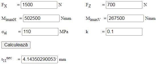
From the bending strength condition, with FX = 1500 N, FZ = 700 N, MîmaxH = 502500 Nmm, MîmaxV = 267500 Nmm, k = 0.1 and σaî = 110 MPa,  = 4.15 mm; a standard square tube with h11 = 60 mm, t11 = 5 mm is adopted, so h12 = 50 mm.
Sizing the left/right bar 12/12′
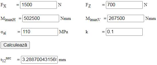
From the bending strength condition, with FX = 1500 N, FZ = 700 N, MîmaxH = 502500 Nmm, MîmaxV = 267500 Nmm, k = 0.1 and σaî = 110 MPa,  = 3.3 mm; a standard square tube with h12 = 50 mm (see above) and t12 = 5 mm is adopted.
Checking
Torsional strength of bars 12/12′
From the torsion check of bars 12/12′, with MY11 = 585000 Nmm, h12 = 50 mm and t12 = 5 mm, the maximum torsional stress is τmax = 26 MPa.
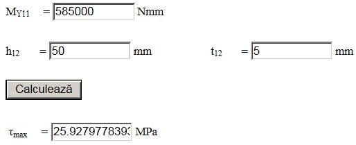
τmax < τat; 26 MPa < 60 MPa (satisfied).
Constructive-technological shape
Constructive-technological drawing
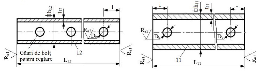
Adopted dimensions and constructive-technological parameters
– section dimensions: h11 = 60 mm, t11 = 5 mm, h12 = 50 mm, t12 = 5 mm; L11 = 550 mm, L12 = Y1/2 + L11-12, l = L11-12/2; the dimension L11-12 is determined from the tube-in-tube joint calculation; the bore diameter Db is determined from the pin joint calculation;
– the number of adjustment pin holes, and hence the adjustment travel, is set when drawing the assembly;
– technological operations: milling (the bar ends) and drilling;
– sharp edges are chamfered 1×45°;
– roughness of the surfaces machined by milling (bar ends) and drilling: Ra1 = 12.5 µm, Ra2 = 6.3 µm.