Design data
External forces: FX = 1500 N, FY = 300 N, FZ = 700 N act at distances Lc = 70 mm; X1 = 80 mm; Z1 = 180 mm and h6 = 60 mm, a = 140 mm; the bending moments at the centre of the flange (the welded joint) are:
MX9 = FY (Lc + Z1) = 75000 Nmm,
MY9 = FX (Lc + Z1) + FZ (X1 + h6/2 + a) = 550000 Nmm,
MZ9 = FY (X1 + h6/2 + a) = 75000 Nmm.
Dimensional constraints: flanges 9 and 10, of thickness g = 10 mm, are connected by 4 bolted joints; the flange dimensions are chosen so as to give access to the wrenches used to tighten the standard bolts and nuts.
Operating constraints: temperature T = (−30…40) °C; outdoor working environment with high humidity.
Design constraints: the flange materials must be weldable; the bolt and nut materials are chosen according to the relevant regulations.
Materials and heat treatments
Since elements 9 and 10 are welded parts, weldable S235 steel according to SR EN 10025-2 (STAS 500/2) is adopted.
For the bolts, property class 6.8 is adopted, with σ02 ≈ 6·8·10 = 480 MPa and σr ≈ 6·100 = 600 MPa.
Material properties
| Material | Heat treatment | Hardness [HB] | Yield strength | Ultimate tensile strength |
|---|---|---|---|---|
| S235 | – | – | σ02 = 235 MPa | σr = 360 MPa |
| Class 6.8 | – | – | σ02 = 480 MPa | σr = 800 MPa |
Sizing
Calculation data
– loading: FX = 1500 N, FY = 300 N, FZ = 700 N; MX9 = 75000 Nmm, MY9 = 550000 Nmm, MZ9 = 75000 Nmm;
– shapes and dimensions: square flange of size Lf = 120 mm; side of the hole-pattern square L = 90 mm; a = (Lf – L)/2 = 15 mm; r1 = r2 = r3 = r4 = r =  L/2 = 63.64 mm;
– material: property class 6.8, σ02 = 480 MPa – the yield strength; c = 2…3 – the safety factor; σat = σ02/c = 480/(2…3) = (160…240) MPa – the allowable tensile stress (σat = 200 MPa adopted);
– friction parameters: µ = 0.2 – the sliding friction coefficient between flanges 9 and 10; µ1 = 0.2 – the sliding friction coefficient in the thread; µ2 = 0.25 – the sliding friction coefficient between nut and washer.
Loads
Finding the most heavily loaded bolt
Axial forces in the bolts due to each load:
– bolt forces due to the force FX, which loads the joint axially and centrically,
 =
=  =
=  =
=  =
=  = 375 N;
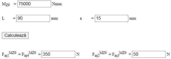
– bolt forces due to the moment MZ9, which loads the joint axially and eccentrically; with MZ9 = 75000 Nmm, L = 90 mm and a = 15 mm,  =
=  = 350 N,
  =
=  = 50 N;
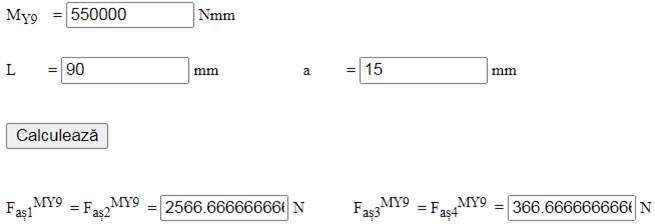
– bolt forces due to the moment MY9, which loads the joint axially and eccentrically; with MY9 = 550000 Nmm, L = 90 mm and a = 15 mm,  =
=  = 2566.7 N,
  =
=  = 366.7 N;
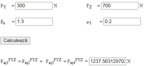
– bolt forces due to the resultant of FY and FZ, which loads the joint transversely and centrically; with FY = 300 N, FZ = 700 N, βa = 1.3 and µ1 = 0.2,  =
=  =
=  =
=  = 1237.5 N;
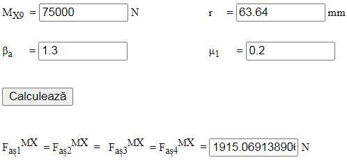
– bolt forces due to the moment MX9, which loads the joint transversely and centrically; with MX9 = 75000 Nmm, r = 63.64 mm, βa = 1.3 and µ1 = 0.2,  =
=  =
=  =
=  = 1915 N;
Total axial forces in the bolts
Faș1 = + + + + = 375 + 350 + 2566.7 + 1237.5 + 1915 = 6444.2 N
Faș2 = + + + + = 375 + 50 + 2566.7 + 1237.5 + 1915 = 6144.2 N
Faș3 = + + + + = 375 + 50 + 366.7 + 1237.5 + 1915 = 3944.2 N
Faș4 = + + + + = 375 + 350 + 366.7 + 1237.5 + 1915 = 4244.5 N
The maximum total axial force, Faș = max(Faș1, Faș2, Faș3, Faș4) = 6444.2 N, shows that bolt 1 is the most heavily loaded; it is sized below.
Axial tightening (preload) force at assembly
Fst = max( + , + , + , + ) = max(1237.5 + 1915, 1237.5 + 1915, 1237.5 + 1915, 1237.5 + 1915) = 3152.5 N.
Sizing
– sizing the most heavily loaded bolt from the tensile strength condition, with Faș = 6444.2 N, β = 1.2 and σat = 200 MPa, gives the required minor thread diameter  = 7.02 mm;

– standard dimensions adopted: d1 = 8.376 mm, pitch diameter d2 = 9.026 mm; d = 10 mm (M10), p = 1.5 mm; clearance hole diameter D1 = 11 mm.
Tightening moments of the joint
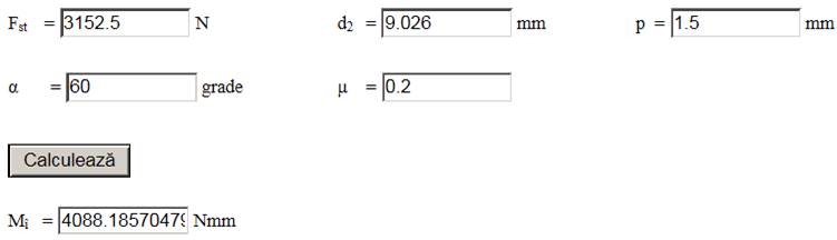
– screwing moment (thread friction): with Fst = 3152.5 N, d2 = 9.026 mm, p = 1.5 mm, µ = 0.2 and α = 60°, Mî = 4088.2 Nmm;
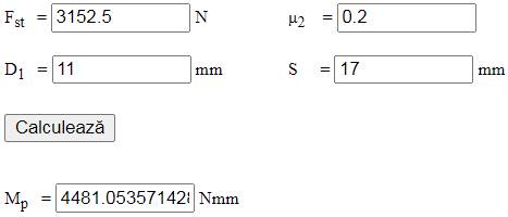
– pivoting friction moment between nut and washer: with Fst = 3152.5 N, D1 = 11 mm, S = 17 mm and µ2 = 0.2, Mp = 4481 Nmm;
– nut tightening (wrench) torque,
Mc = Mî + Mp = 4088.2 + 4481 = 8569.2 Nmm.
Checks
– checking the threaded bolt shank under combined loading (tension and torsion) when tightened under load (the most unfavourable case): with Faș = 6444.2 N, d1 = 8.376 mm and Mî = 4088.2 Nmm, σe = 136.7 MPa,
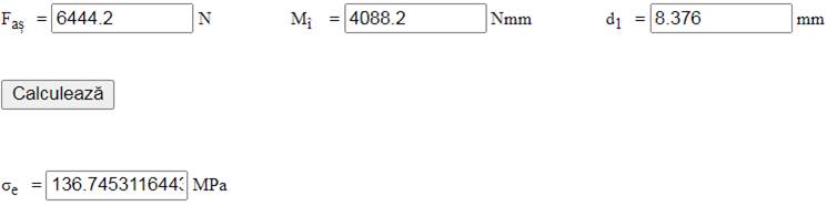
and 136.7 < (160…240) MPa (satisfied).
– checking the self-locking condition: with p = 1.5 mm, d2 = 9.026 mm, μ = 0.2 and α = 60°, β2 = 3.03°, φ′ = 13°,
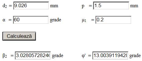
and 3.03° < 13° (satisfied).
Design of the technological shape
Constructive-technological drawing
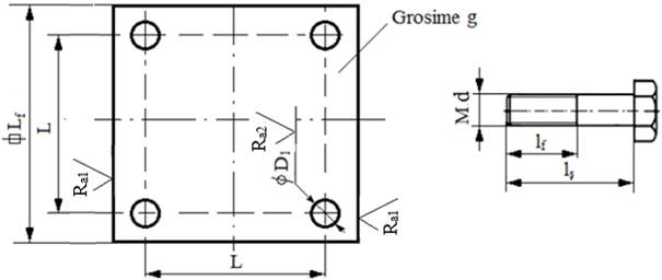
Adopted dimensions and constructive-technological parameters
– dimensions: Lf = 120 mm, L = 90 mm, g = 10 mm, D1 = 11 mm;
– roughness of the surfaces machined by milling and drilling: Ra1 = 12.5 µm; Ra2 = 6.3 µm;
– sharp edges are chamfered 1×45°.
Adopted fastener dimensions
– hexagon head bolt: M10, d = 10 mm, S = 17 mm, D = 18 mm, k = 7 mm, lș = 40 mm, lf = 25 mm;
– hexagon nut: M10, S = 17 mm, m = 8 mm;
– flat washer: d = 10 mm, d1 = 10.5 mm, d2 = 20 mm, h = 2 mm;
– Grower spring washer: MN 10, d1 = 10.2 mm, d2 = 15.2 mm, g = 2.5 mm.