A. Loading diagram and design data
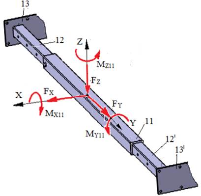
External loading diagram
|
Loading diagram of elements 11, 12, 12′ |
 |
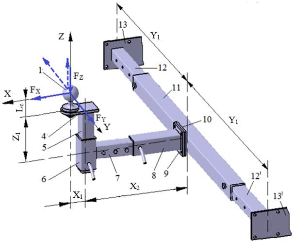
Design data
External forces: FX, FY, FZ act at distances Lc (Ex.3.1), X1, X2, Y1, Z1 (Ex.1.2.2); the moments at the centre of bar 11 are calculated (Calc.0):
MX11 = FY (Lc + Z1),
MY11 = FX (Lc + Z1) + FZ (X1 + X2),
MZ11 = FY (X1 + X2).
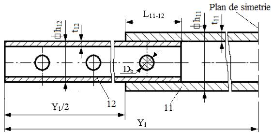
Dimensional constraints: square tube 12 slides into square tube 11 with clearance fits.
Operating constraints: temperature T = (−30…40) °C; outdoor working environment with high humidity.
Design constraints: weldable materials for elements 11, 12 and 12′.
B. Choice of material and heat treatments
Since elements 11, 12, 12′ are welded parts, a weldable steel is adopted (e.g. S185, S235, S275; Annex.M.01), according to SR EN 10025-2 (STAS 500/2). These steels are not heat-treated before welding; after welding, the subassemblies may undergo stress-relief annealing. For the adopted steel, the yield strength σ02 and the ultimate tensile strength σr are retained for the calculations.
C. Design of the constructive shape
Constructive model
|
Constructive features and constraints – for minimum weight, standard square tube semi-finished products are adopted; – square tube 11 is T-welded to flange 10, whose thickness g equals that of flange 9 (Ex.4.3); – the length of tube 11 is taken as Y1/2. |
D. Calculation model, sizing and checking
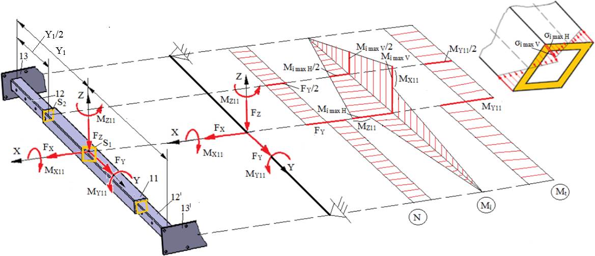
Calculation model
Calculation assumptions and loads
– the calculation model is a straight bar supported at its ends, made of 2 square tubes, loaded in tension by FY, in oblique bending by FZ, FX and MX11, MZ11, in torsion by MY11, and in shear by FX and FZ;
– elements 11 and 12/12′ form tube-in-tube joints and are fixed axially by pin joints;
– for the strength calculation, the assembly of the three elements is considered rigidly connected to the tie rods 13/13′;
– since a sizing model accounting for all loads is quite complex, a simplified model is adopted, which neglects the stresses from the axial and shear forces and from the torsional moment and considers the bending loads generated by the maximum orthogonal moments in the horizontal and vertical planes, MîmaxH and MîmaxV respectively; once the dimensions have been obtained from the simplified model, they are checked with the MDESIGN package (Guide.6.3, Ex.6.3).
Calculation data
– loading: FX, FY, FZ, MX11, MZ11, MY11;
– shape and dimensions: inner square tube with dimensions h12, t12; outer square tube with dimensions h11, t11;
– material: σ02 – the yield strength; c = 2…3 – the safety factor; σat = σ02/c = 235/(2…3) = (78.33…117.5) MPa – the allowable tensile stress (σat = 100 MPa adopted); σaî = (1.05…1.1)σat = (105…110) MPa – the allowable bending stress (σaî = 110 MPa adopted); τat = 40…80 MPa – the allowable torsional stress.
Calculation relations
– bending moments in the critical sections (simplified model):
MîmaxH = MZ11 + FX Y1/2, (Calc.0)
MîmaxV = MX11 + FZ Y1/2, (Calc.0)
in section S1, and MîmaxH/2, MîmaxV/2 in section S2.
– bending strength conditions in the critical sections S1 and S2, with t11/h11 = t12/h12 = k,
σîmax_S1 = σî_S1_H + σî_S1_V =  +
+  =
= 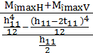 =
= 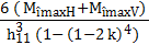 ≤ σaî
≤ σaî
and, respectively,
σîmax_S2 = σî_S2_H + σî_S2_V =  +
+  =
= 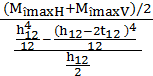 =
= 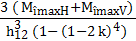 ≤ σaî.
Sizing
– sizing the central bar 11: from the last part of the relation for σîmax_S1,
 = k
= k 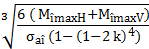 (Calc.6.1.1)
and a square tube with standard dimensions h11 and t11 ≥ is chosen from Annex.ST.02, with h12 = h11 − 2t11.
– sizing the left/right bar 12/12′: from the last part of the relation for σîmax_S2,
 = k
= k 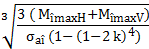 (Calc.6.1.2)
and a square tube with standard dimensions h12 (determined above) and t12 ≥ is chosen from Annex.ST.02.
Checking
Torsional strength of bars 12/12′, according to
τmax =  =
= 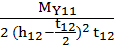 ≤ τat. (Calc.6.1.3)
E. Design of the constructive-technological shape
Constructive-technological drawings
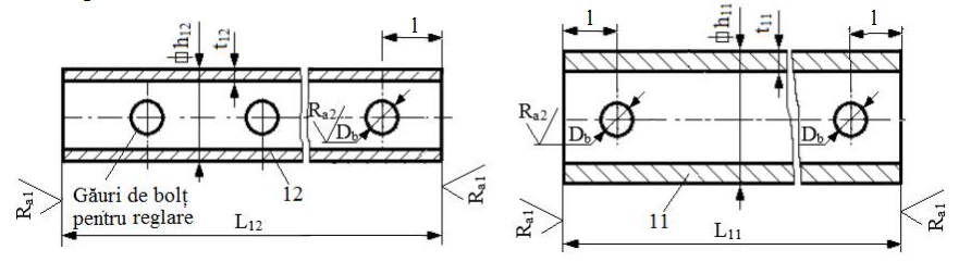
Recommendations for choosing the dimensions and constructive-technological parameters
– section dimensions: h11, t11, h12, t12, L11 = Y1, L12 = Y1/2 + L11-12, l = L11-12/2; the dimension L11-12 is determined from the tube-in-tube joint calculation (Sec.6.2, Ex.6.2); the bore diameter Db is determined from the pin joint calculation (Sec.6.7, Ex.6.7);
– the number of adjustment pin holes, and hence the adjustment travel, is set when drawing the assembly;
– technological operations: milling (the bar ends) and drilling;
– sharp edges are chamfered 1×45°;
– roughness of the surfaces machined by milling (bar ends) and drilling: Ra1 = 6.3 µm or Ra1 = 12.5 µm; Ra2 = 6.3 µm or Ra2 = 12.5 µm.