A. Loading diagram and design data
External loading diagram
|
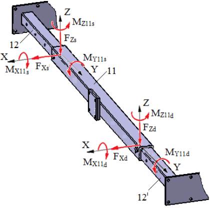
Loading diagram of joints 11-12, 11-12′ |
 |
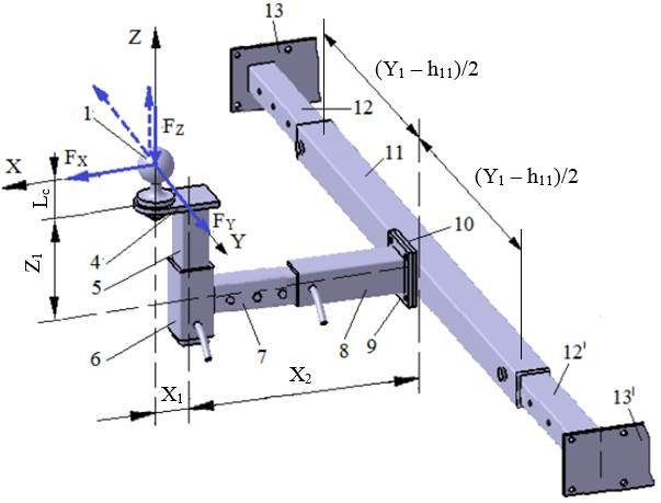
Design data
External forces: FX, FY, FZ act at distances Lc (Ex.3.1), X1, X2, Y1, Z1 (Ex.1.2.2), with the size of bar 11, h11 (Ex.6.1); the forces and moments at the centres of the joints are calculated (Calc.0):
FXs = FXd = FX/2,
FZs = FZd = FZ/2 and, respectively,
MX11s = MX11d = FY (Lc + Z1)/2 + FZ (Y1 − h11)/2,
MY11s = MY11d = FX (Lc + Z1)/2 + FZ (X1 + X2)/2,
MZ11s = MZ11d = FY (X1 + X2) + FX (Y1 − h11)/2.
Note. Since the forces FX, FY and FZ can act in both directions during operation of the towing device, the combinations giving the maximum values were used when calculating the moments.
Dimensional constraints: the square tubes 12, 12′, of side h12 and thickness t12 (Ex.6.1), are assembled with the square tube 11, of side h11 and thickness t11 (Ex.6.1).
Operating constraints: temperature T = (−30…40) °C; outdoor working environment with high humidity.
Design constraints: tubes 12, 12′ are inserted into tube 11, with clearance fits on the sides of the squares in contact.
B. Choice of material and heat treatments
Since elements 12, 12′ and 11 are welded to other elements, weldable steels were adopted (Annex.M.01). For the adopted steels, the yield strength σ02, the ultimate tensile strength σr and the allowable crushing stress σas = 60…90 MPa for conforming steel-on-steel contacts are retained for the calculations.
C. Design of the constructive shape
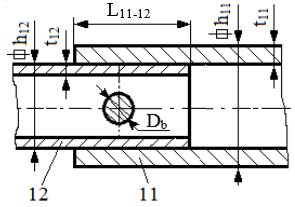 |
Constructive features and constraints – for correct operation, conforming contacts (over large surfaces) are required between tubes 12, 12′ and 11; they are obtained by a clearance fit; – the pin joints are placed in the middle of the contact zone of the tube-in-tube joint. |
D. Calculation model and sizing
Diagram of the joint between elements 5-6
|
Diagram of the joint between elements 11-12
|
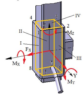
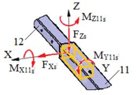
Specific features of joint 11-12 (11-12′)
– the calculation model of the joint between square tubes 11 and 12 is similar to that of the joint between tubes 5 and 6, with the following differences related to the coordinate systems:
– the coordinate system of joint 11-12 has Y as the axial axis instead of Z, and Z as the transverse axis instead of Y;
– the size of the square bore is H = h12.
Calculation data
– loads: FX = FXs, FY = FZs, FZ = FXs, MX = MX11s, MY = MZ11s, MZ = MY11s;
– dimensions: the size of the contact square H = h12; the wall thickness of the inner tube t12 and of the outer tube t11; the length L is unknown;
– materials: σas = 60…90 MPa – the allowable crushing stress.
Sizing
With calculation window Calc.4.1.1, after substituting the known parameters and solving, two positive solutions are usually obtained.
Finally, L11-12 is taken as the largest positive value of L (rounded up to a whole value).
E. Design of the technological shape
Constructive-technological drawings
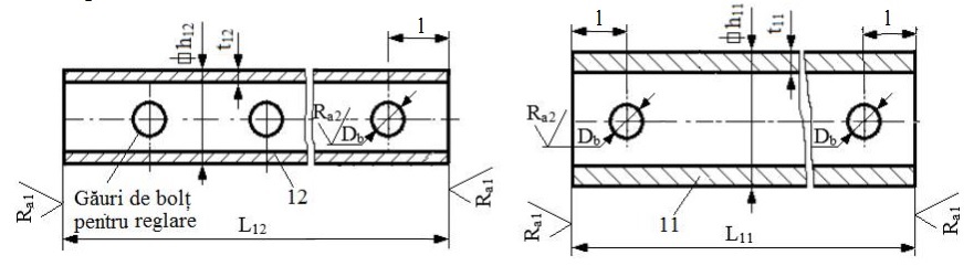
Recommendations for choosing the dimensions and constructive-technological parameters
– section dimensions: h11, t11, h12, t12, L11 = Y1, L12 = Y1/2 + L11-12, l = L11-12/2; the bore diameter Db is determined from the pin joint calculation (Sec.6.7, Ex.6.7);
– the number of adjustment pin holes, and hence the adjustment travel, is set when drawing the assembly;
– technological operations: milling (the bar ends) and drilling;
– sharp edges are chamfered 1×45°;
– roughness of the surfaces machined by milling (bar ends) and drilling: Ra1 = 6.3 µm or Ra1 = 12.5 µm; Ra2 = 6.3 µm or Ra2 = 12.5 µm.