Design data
External forces: FY = 300 N; FYs = FY/2 = 150 N.
Dimensional constraints: the square tube 12, 12′, of side h12 and thickness t12 = 5 mm, is assembled with the square tube 11, of size h11 = 60 mm and thickness t11 = 5 mm.
Operating constraints: temperature T = (−30…40) °C; outdoor working environment with high humidity.
Design constraints: dimensional interchangeability.
Materials and heat treatments
A weldable material, S235 steel according to SR EN 10025-2 (STAS 500/2), was chosen for elements 11, 12 and 12′.
The pin is made of steel for mechanical construction, e.g. E295, E335, E360 (SR EN 10025/2005), or even of a quenching-and-tempering steel C35, C40, C45.
For each material identify: the yield strength σ02; the ultimate tensile strength σr; the allowable shear stress τaf = 60 MPa; the allowable steel-on-steel crushing stress σas = 70 MPa (lower values are adopted for mild steels).
Sizing and checking
Sizing
From the sizing relation obtained from the crushing strength condition, with F = FYs = 150 N, thicknesses t12 = 5 mm and t11 = 5 mm, σasț = 60 MPa and σasb = 70 MPa,  = 0.53 mm.
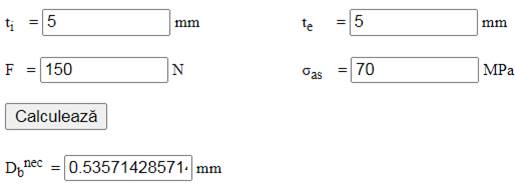
For technological reasons, Db = 8 mm is adopted.
Checking
Shear check, with Db = 8 mm:
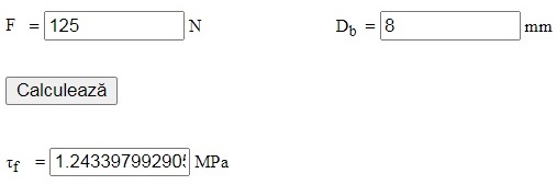
and the check τf ≤ τaf becomes 0.8 ≤ 60 MPa (satisfied).
Constructive-technological shape
Constructive-technological drawing
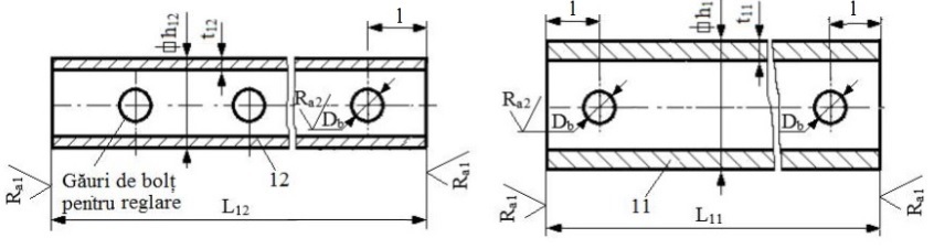
Adopted dimensions and constructive-technological parameters
– section dimensions: h11 = 60 mm, t11 = 5 mm, h12 = 50 mm, t12 = 5 mm; L11 = 550 mm, L12 = 345 mm, Db = 8 mm;
– the number of adjustment pin holes, and hence the adjustment travel, is set when drawing the assembly;
– technological operations: milling (the bar ends) and drilling;
– sharp edges are chamfered 1×45°;
– roughness of the surfaces machined by milling (bar ends) and drilling: Ra1 = 12.5 µm, Ra2 = 6.3 µm.
Adopted fastener dimensions
– pin: d = 8 mm, l = 70 mm;
– retaining ring for shafts: d2 = 7 mm, s = 0.9 mm;
– washer for pins: d = 8 mm, d1 = 16 mm, h = 2 mm.