A. Loading diagram and design data
External loading diagram
|
Loading diagram of the welded joint 8-9 |
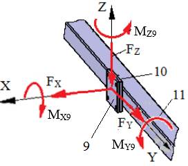 | |
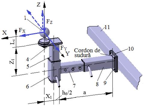
Design data External forces: FX, FY, FZ act at distances Lc (Ex.3.1), X1, Z1 (Ex.1.2.2), h6 (Ex.4.1) and a (Ex.5.1); the moments at the centre of the square section are calculated (Calc.0): MX9 = FY (Lc + Z1), MY9 = FX (Lc + Z1) + FZ (X1 + h6/2 + a), MZ9 = FY (X1 + h6/2 + a). Dimensional constraints: the lower column body 8 is welded to flange 9, with dimensions h8, t8, g (Ex.4.3). Operating constraints: temperature T = (−30…40) °C; outdoor working environment with high humidity. Design constraints: weldable materials for elements 8 and 9. | |
B. Choice of material and heat treatment
Element 8 was designed in weldable steel (Annex.M.01). A weldable steel is also adopted for element 9. These steels are not heat-treated before welding; after welding, the subassembly may undergo stress-relief annealing. For the adopted steels, the yield strengths σ02 and the ultimate tensile strengths σr are retained for the calculations.
C. Design of the constructive shape
Constructive model
Constructive features and constraints
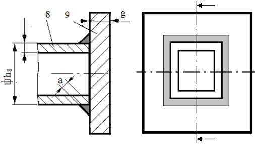
– the weld throat thickness a should be smaller than the wall thickness t8 of tube 8 and the thickness g of flange 9 (a < min(t8, g));
– the two elements must be perpendicular;
– a fillet weld is made along the closed contour (the square section).
D. Calculation model and sizing
Calculation model
The calculation model is similar to the general model in Sec.3.5.
Calculation data
– loading: FXs = FZ, FYs = FX, FZs = FY; MXs = MZ9; MYs = MX9; MZs = MY9;
– shape and dimensions: the inner contour of the weld bead is a square of side h = h8;
– materials: σ02 – the yield strength; c = 2…3 – the safety factor; σat = σ02/c – the allowable tensile stress; τafs = (0.6…0.7)σat – the allowable shear stress of the weld.
Sizing
The weld throat thickness anec is determined with calculation window Calc.3.5.1; a whole value a > anec is adopted.
E. Design of the constructive-technological shape
Constructive-technological drawing
|
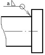
Recommendations for choosing the dimensions and technological parameters: – weld throat thickness, a; – the weld is made along the closed contour (as symbolised); – after welding, the subassembly undergoes stress-relief annealing. |