Design data
External forces: FX = 1500 N, FY = 300 N, FZ = 700 N act at distances Lc = 70 mm; X1 = 80 mm; Z1 = 180 mm and h6 = 60 mm, h8 = 60 mm, a = 140 mm; the bending moments at the centre of the flange (the welded joint) are:
MX9 = FY (Lc + Z1) = 75000 Nmm,
MY9 = FX (Lc + Z1) + FZ (X1 + h6/2 + a) = 550000 Nmm,
MZ9 = FY (X1 + h6/2 + a) = 75000 Nmm.
Dimensional constraints: the lower column body 8 is welded to flange 9, with dimensions h8 = 60 mm and thicknesses t8 = 5 mm, g = 10 mm.
Operating constraints: temperature T = (−30…40) °C; outdoor working environment with high humidity.
Design constraints: weldable materials for elements 8 and 9.
Materials and heat treatments
Elements 8 and 9 were designed in weldable S235 steel according to SR EN 10025-2 (STAS 500/2).
Material properties
| Material | Heat treatment | Hardness [HB] | Yield strength | Ultimate tensile strength |
|---|---|---|---|---|
| S235 | – | – | σ02 = 235 MPa | σr = 360 MPa |
Sizing
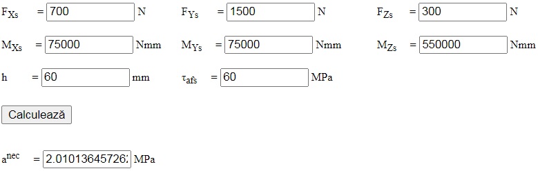
From the sizing relation obtained from the shear strength condition of the weld, with FXs = FZ = 700 N, FYs = FX = 1500 N, FZs = FY = 300 N; MXs = MZ9 = 75000 Nmm, MYs = MX9 = 75000 Nmm, MZs = MY9 = 550000 Nmm; h = h8 = 60 mm; σat = 235/(2…3) = (78.33…117.5) MPa, σat = 100 MPa adopted; τafs = (0.6…0.7)σat = (60…70) MPa, τafs = 60 MPa adopted; the weld throat thickness is anec = 2.01 mm; a = 3 mm is adopted.
Constructive-technological shape
Constructive-technological drawing
|
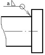
Adopted dimensions and constructive-technological parameters: – weld throat thickness a = 3 mm; – the weld is made along the closed contour (as symbolised); – after welding, the subassembly undergoes stress-relief annealing. |