A. Loading diagram and design data
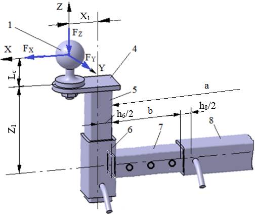
External loading diagram
|
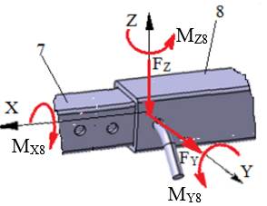
Loading diagram of joint 7-8 |
 |
Design data
External forces: FX, FY, FZ act at distances Lc (Ex.3.1), X1, Z1 (Ex.1.2.2), h6 (Ex.4.1), h7, h8, a, b (Ex.4.3); the moments at the centre of the joint are calculated (Calc.0):
MX8 = FY (Lc + Z1),
MZ8 = FY (X1 + h6/2 + b + h8/2),
MY8 = FX (Lc + Z1) + FZ (X1 + h6/2 + b + h8/2).
Dimensional constraints: the square tubes 7 and 8, with sides h7, h8 and wall thicknesses t7, t8 (Ex.4.3), are assembled together.
Operating constraints: temperature T = (−30…40) °C; outdoor working environment with high humidity.
Design constraints: tube 7 is inserted into tube 8, with loose clearance fits on the sides of the squares in contact.
B. Choice of materials
Since elements 7 and 8 are welded to other elements, weldable steels are adopted (Annex.M.01). For the adopted steels, the yield strength σ02, the ultimate tensile strength σr and σas = 60…90 MPa, the allowable crushing stress for conforming steel-on-steel contacts, are retained for the calculations.
C. Design of the constructive shape
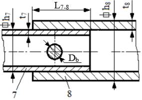 |
Constructive features and constraints: – for correct operation, conforming contacts (over large surfaces) are required, ensured by the tube dimensions; – the dimensions of the pin joint are determined from the pin joint calculation (Sec.5.2, Ex.5.2). |
D. Calculation model, sizing and checking
Model of the joint between elements 5-6 (Sec.4.1)
|
Model of the joint between elements 7-8
|
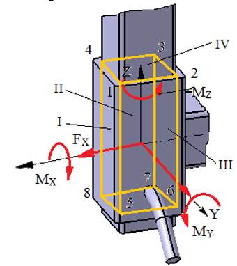
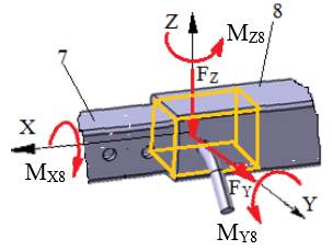
Specific features of the model of joint 7-8
The calculation model of the joint between square tubes 7 and 8 is similar to the (general) calculation model of the joint between tubes 5 and 6 (Sec.4.1), with the following differences related to the coordinate systems:
– the coordinate system of joint 7-8 has X as the axial axis instead of Z, and Z as the transverse axis instead of X;
– the size of the square bore is H = h7.
Calculation data
– loads: FX = FZ, FY, MX = MZ8, MY = MY8, MZ = MX8;
– shapes and dimensions: the size of the square bore H = h7; the wall thickness of the inner tube t7 and of the outer tube t8; the length L of the contact prism is unknown;
– materials: σas = 60…90 MPa – the allowable crushing stress.
Sizing
With calculation window Calc.4.1.1, after substituting the known parameters and solving, two positive solutions are usually obtained.
Finally, L7-8 is taken as the largest positive value of L (rounded up to a whole value).
E. Design of the constructive-technological shape
Constructive-technological drawings
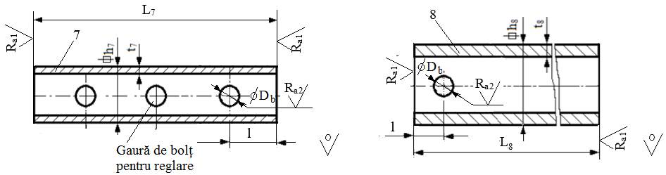
Recommendations for choosing the dimensions and constructive-technological parameters
– dimensions: h7, t7, h8, t8, L7 = b + h8/2 + L7-8/2, L8 = a – L7 + L7-8, l = L7-8/2; the pin bore diameter Db is determined from the pin joint calculation (Sec.5.2, Ex.5.2); Note. If L7 > a or L8 < 0, the tube-in-tube joint cannot be integrated because larger dimensions would be needed, so it is dropped (together with element 8 and the pin);
– technological operations: milling the tube ends, drilling/reaming the pin holes;
– roughness of the machined surfaces: Ra1 = 6.3 µm or Ra1 = 12.5 µm; Ra2 = 6.3 µm or Ra2 = 3.2 µm;
– sharp edges are chamfered 1×45°;
– the position of the pin hole (and, if needed, of the adjustment pin hole) is set when drawing the assembly.