A. Loading diagram and design data
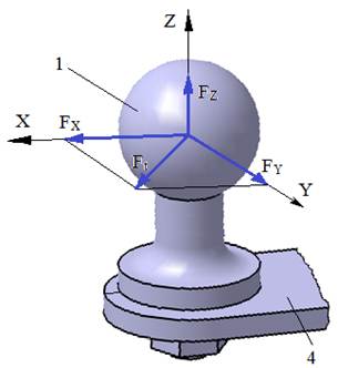
Loading diagram
|
Design data External forces: FX, FY, FZ; the transverse force is calculated (Ex.3.1). Operating constraints: temperature T = (−30…40) °C; outdoor working environment with high humidity. Design constraints: – type of fit of the threaded shank: clearance fit; – fastening thread: metric; – nut type: standard hexagon nut; – flat washer to provide the bearing surface of the nut; – Grower spring washer to prevent loosening during operation. |
B. Choice of materials and heat treatments
Hook material
C45 (0.45 % C), quenched and tempered (quenching and high tempering), with hardness HB, yield strength σ02 and ultimate tensile strength σr (Ex.3.1).
Nut material
Property class x, with x = 6, 8, 10 (σr ≈ 600, 800, 1000 MPa).
Note. The usual property class symbols for nuts are 4, 5, 6, 8, 10, 12; meaning: the number × 100 = minimum ultimate tensile strength (σrmin) in MPa (e.g. for class 8, σr = 8 × 100 = 800 MPa).
Contact properties of the materials
Since all the materials of the elements in contact are steels, the following are adopted: allowable steel-on-steel crushing (bearing) stress σas = 60…90 MPa; steel-on-steel friction coefficients μ = 0.15…0.25, μ1 = 0.15…0.25, μ2 = 0.15…0.25.
C. Design of the constructive shape
Constructive drawings
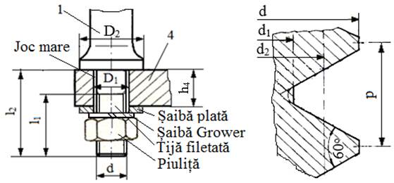
Parameters: d – nominal thread diameter, d1 – minor thread diameter, d2 – pitch diameter, p – thread pitch; D1 – clearance hole diameter, D2 – collar diameter, l1 – length of the threaded portion, l2 – length of the joint portion.
Constructive features and constraints
– thickness of element 4, h4 (Ex.3.2);
– collar diameter, D2 (Ex.3.1).
D. Calculation model, sizing and checking
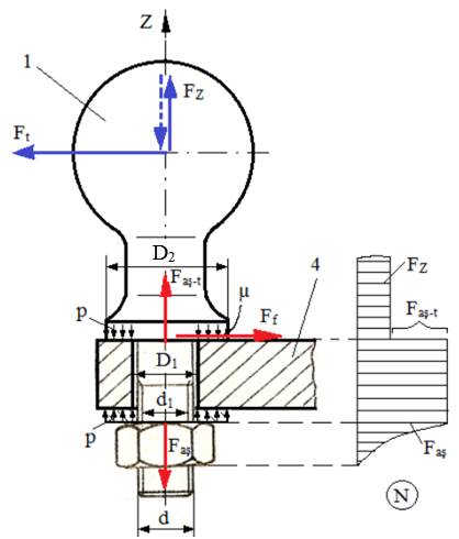
Calculation model
Calculation assumptions
– the threaded shank is treated as a straight bar fixed in the body of the towing hook, with a constant circular cross-section of diameter d1 (the minor thread diameter), loaded in tension by the axial force Faş;
– the torque that arises when tightening the joint, and therefore the associated shear stresses, are neglected;
– the external force FZ, which may act in both directions during operation, is assumed for this calculation to act in the positive direction of the Z axis, which places an additional load on the bolted joint;
– the transverse force Ft is transmitted by friction from element 1 to element 4 over a single contact surface.
Calculation data
– loading: FZ – the vertical force, Ft – the transverse force;
– shape and dimensions: element 4 is a flat bar of thickness h4;
– material: strength properties: σ02 – the yield strength; σat = σ02/c – the allowable tensile stress; c = 2…3 – the safety factor; σas = (60…90) MPa – the allowable steel-on-steel crushing stress; μ1 = 0.15…0.25 – the friction coefficient on the contact surfaces 1-4; μ2 = 0.15…0.25 – the friction coefficient on the nut–washer contact surfaces; μ = 0.15…0.25 – the friction coefficient in the thread.
Calculation relations for sizing the threaded shank
– the axial force in the bolt Faș-t, from the condition of transmitting the force Ft by friction,
βaFt ≤ Ff,
taking the friction force Ff = μ1Faș-t, is given by
Faș-t = βa  , (Calc.3.3.1)
where βa = 1.1…1.3 is the safety factor against slipping and μ1 = 0.15…0.25 is the friction coefficient on the contact surface 1-4;
– the total axial force in the threaded shank (when FZ acts upwards),
Faș = Faș-t + FZ; (Calc.0)
– sizing: from the tensile strength condition of the threaded shank,
σt =  ≤ σat,
the required minor thread diameter is obtained,
 =
=  , (Calc.3.3.2)
where σat = σ02/c [MPa] (Calc.0) is the allowable tensile stress, σ02 the yield strength, c = 2…3 the safety factor, and β = 1.1…1.3 a correction factor (it accounts for the additional torsion that arises when the nut is tightened).
Choosing the dimensions of the standard metric thread
From Annex.ST.03 a metric thread with d1 ≥ is adopted, with the dimensions d1 (minor diameter), d2 (pitch diameter), d (nominal diameter), p (pitch); the clearance hole diameter D1 (medium series), matched to the thread size d, is taken from Annex.ST.05.
Note. It is recommended to adopt coarse-pitch threads (marked in bold), which are the ones most commonly used in practice.
Calculation relations for sizing the collar
From the crushing strength condition of the materials in the contact zone between elements 4 and 1, the contact pressure is
p =  =
=  ≤ σas,
from which the collar diameter, i.e. the minimum outer diameter of the flat washer, is obtained,
D2 = 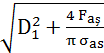 , (Calc.3.3.3)
where σas is the allowable crushing stress of the materials in contact; the following dimensions are adopted: flat washer d1, d2, h (Annex.ST.06); nut d, S, m (Annex.ST.04); Grower washer d1, g (Annex.ST.07).
Relations for calculating the moments
– the screwing (tightening) moment in the thread,
Mî = Fst  tg(arctg
 + arctg
 ), (Calc.3.3.4)
where d2 is the pitch diameter of the thread, p the thread pitch, μ the friction coefficient in the thread and α the profile angle of the metric thread (α = 60°).
– the pivoting (friction) moment on the bearing face of the nut,
Mp = Fst  μ2
μ2  , (Calc.3.3.5)
where μ2 = 0.15…0.25 is the friction coefficient on the nut–washer contact surface, S the wrench size of the nut and D1 the clearance hole diameter.
– the wrench torque for tightening the nut,
Mc = Mî + Mp. (Calc.0)
Checking relations
– checking the threaded shank under combined loading (tension and torsion) at tightening,
σe ≤ σat,
where
σe = 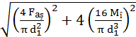 (Calc.3.3.6)
and σat = σ02/c is the allowable tensile stress, σ02 the yield strength and c = 2…3 the safety factor.
Note. If the inequality above is not satisfied, larger dimensions of the standard metric thread are chosen from Annex.ST.03 and the calculations are repeated from the step Choosing the dimensions of the standard metric thread.
– checking the self-locking condition,
β2 ≤ φ′,
where β2 = arctg is the mean helix angle of the thread and φ′ = arctg the reduced friction angle in the thread. (Calc.3.3.7)
E. Design of the constructive-technological shapes
Towing hook, 1
Constructive-technological drawing
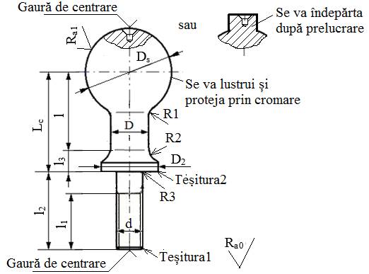
Recommendations for choosing the dimensions and technological parameters
– dimensions obtained: Ds, D, l, Lc, l3 = (0.4…0.6)D, D2, d, l1, l2;
– transition zones are made with fillets R1, R2, R3 (Annex.T.02);
– protective or technological chamfers are adopted: Chamfer1, Chamfer2 (Annex.T.02);
– centre hole (Annex.T.01);
– machining involves: turning, drilling, threading and grinding of the spherical surface;
– roughness of the spherical surface: Ra1 = 3.2 µm or Ra1 = 1.6 µm; general surface roughness: Ra0 = 6.3 µm (Annex.T.03);
– since the element works in a corrosive environment, the spherical surface is protected by chrome plating to preserve its quality throughout the service life.
Upper tie rod, 4
Constructive-technological drawing
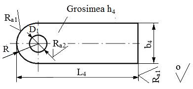
Recommendations for choosing the dimensions and technological parameters
– dimensions: b4, h4, R = b4/2, L4 = X1 + R; D1 is determined when designing joint 1-4;
– protective chamfers are adopted on sharp edges (Annex.T.02);
– machining involves milling the end portions and drilling; the other surfaces remain unmachined, as indicated by the attached symbol;
– roughness of the machined surfaces: Ra1 = 6.3 µm or Ra1 = 12.5 µm; Ra2 = 6.3 µm or Ra2 = 12.5 µm (Annex.T.03).
Fasteners
Recommendations for choosing the dimensions
– nut: d, S, m (Annex.ST.04);
– flat washer: d1, d2, h (Annex.ST.06);
– Grower spring washer: d1, g (Annex.ST.07).