A. Loading diagram and design data
Loading diagram
|
Design data External forces: FX, FY, FZ; the transverse force is calculated as Ft = Operating constraints: temperature T = (−30…40) °C; outdoor working environment with high humidity. Design constraints: interchangeability with the coupling systems in use in the EU. Note. The straight-shank coupling ball (Annex.3.1.1) connects to the coupling head (Annex.3.1.2) with permanent contact on a spherical surface; this contact is maintained by a locking element (latch). |
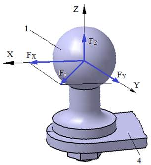
 (
(B. Choice of material (Annex.M.01)
Since the straight-shank coupling ball is an important part of the ATD, a quality non-alloy carbon steel for quenching and tempering is adopted: C45, C55, C60, according to SR EN 10025-2 (STAS 500/2). For the adopted steel, the hardness, the yield strength σ02 and the ultimate tensile strength σr after quenching and tempering are retained for the calculations.
C. Design of the constructive shape
Constructive model
|
Choice of hook type A detachable straight coupling ball is adopted (EU variant, Ds = 50 mm), fastened by a thread (standard nut) and secured with a Grower spring washer. Choice of the functional and constructive geometric parameters – to ensure the interchangeability of ball couplings and constructive modularity, coupling devices with a ball diameter Ds = 50 mm (EU variant) have been developed (Annex.3.1.1); – to allow the three relative rotations in the vertical plane at rotation angles of ±(60°…65°), the limiting complementary angle must be αa = 25°…30°; – length of the hook shank, l = (0.8…1.2)Ds; – the height of the bearing collar can be taken as l3 = (0.4…0.6)D; D is determined by sizing according to the model below. Note. Dimension h, as well as d, D1, l1, l2, result from the design of element 4 (Sec.3.2; Ex.3.2) and from the design of joint 1-4 (threaded joint) (Sec.3.3; Ex.3.3), respectively. |
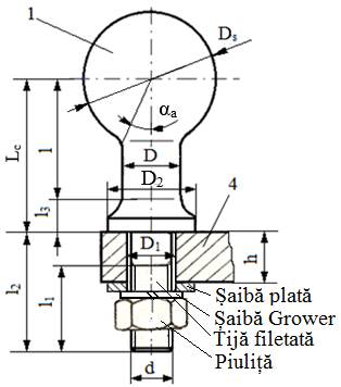
D. Calculation model, sizing and checking
Calculation model
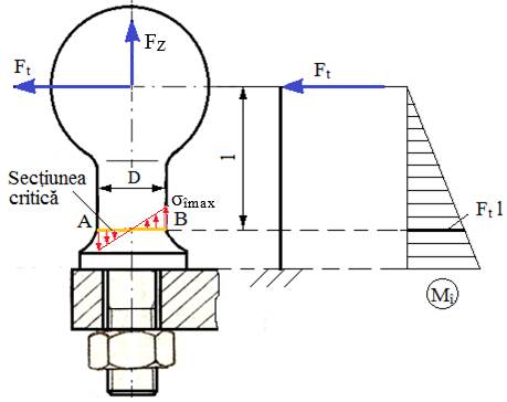
Loads and calculation assumptions
– calculation model: straight cantilever bar of circular cross-section with diameter D, loaded in tension by the force FZ, and in bending and shear by the force Ft;
– the shear stresses generated by Ft and the tensile stresses generated by FZ are neglected.
Calculation relations
– bending moment in the critical section: Mî = Ft l;
– bending strength condition in the critical section A-B,
σîmax =  =
=  =
=  ≤ σaî;
– sizing: from the last part of the relation above,
D =  , (Calc.3.1.2)
where: D [mm] is the diameter of the hook shank (rounded up to a whole number); Ft [N] – the transverse force; l = (0.7…1.3) Ds [mm] – the length of the hook shank; σat = σ02/c – the allowable tensile stress; σaî = (1.05…1.1)σat [MPa] – the allowable bending stress; σ02 – the yield strength; c = 2…3 – the safety factor.
– checking the rotation stroke of the coupling head
D ≤ Ds sin αa, (Calc.0)
where D is the hook-shank diameter determined above, and Ds and αa are as in step C. If this inequality is not satisfied, the sizing (previous step) is repeated with a longer hook shank l.
E. Design of the constructive-technological shape
Constructive-technological drawing
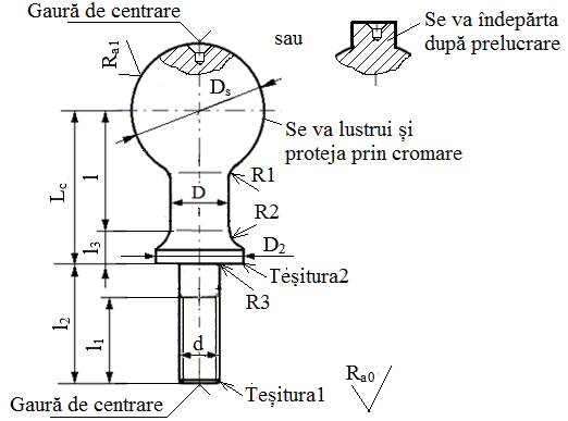
Recommendations for choosing the dimensions and technological parameters
– dimensions: Ds, D, l, Lc; l3 = (0.4…0.6)D; the other dimensions are determined after designing the upper tie rod 4 (Sec.3.2, Ex.3.2) and joint 1-4 (Sec.3.3, Ex.3.3);
– transition zones are made with fillets R1, R2, R3 (Annex.T.02);
– protective or technological chamfers are adopted: Chamfer1, Chamfer2 (Annex.T.02);
– choice of the centre hole (Annex.T.01);
– machining involves: turning, drilling, threading and grinding of the spherical surface;
– surface quality (roughness) of the spherical surface: Ra1 = 3.2 µm or Ra1 = 1.6 µm; general surface roughness: Ra0 = 6.3 µm (Annex.T.03);
– since the element works in a corrosive environment, the spherical surface is protected by chrome plating to preserve its quality throughout the service life.