Definition
Static analysis means determining the action/reaction forces and moments between the elements/subassemblies of the ATD, without taking dynamic loads into account. This requires knowing the dimensions of the elements, whose values are determined by going successively through the stages of the Main design algorithm. At this stage, therefore, only diagrams showing the interaction forces/moments can be drawn.
Diagram of the interaction forces/moments at the level of subassemblies and input/output elements
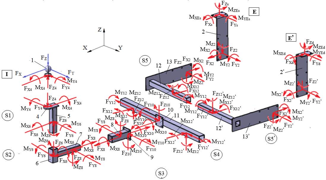
Notes.
– When marking (in red) the forces/moments in the joints, the action–reaction principle was observed (the forces and moments have the same magnitudes and directions, but opposite senses).
– The interaction forces can be determined going from the input (I) towards the output (E) as follows:
FX4 = FX, FY4 = FY, FZ4 = FZ;
FX6 = FX, FY6 = FY, FZ6 = FZ;
FX8 = FX, FY8 = FY, FZ8 = FZ;
FX10 = FX, FY10 = FY, FZ10 = FZ;
FX12 = FX/2, FY12 = FY/2, FZ12 = FZ/2; FX12′ = FX/2, FY12′ = FY/2, FZ12′ = FZ/2;
FX2 = FX/2, FY2 = FY/2, FZ2 = FZ/2; FX2′ = FX/2, FY2′ = FY/2, FZ2′ = FZ/2;
FXs = FX/2, FYs = FY/2, FZs = FZ/2; FXd = FX/2, FYd = FY/2, FZd = FZ/2.
– The values of the moments are determined as the stages of the Main design algorithm are worked through.