A. Loading diagram and design data
External loading diagram
|
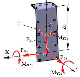
Loading diagram of element 2 |
 |
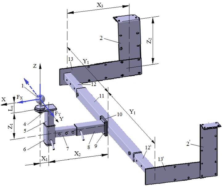
Design data
External forces: FX, FY, FZ act at distances Lc (Ex.3.1), X1, X2, X3, Y1, Z1, Z2 (Ex.1.2.2); the forces and moments at the centre of joint 13-2 are calculated (Calc.0):
FXs = FX/2,
FYs = FY/2,
FZs = FZ/2;
MX2s = FY (Lc + Z1)/2 + FZ Y1/2,
MY2s = FX (Lc + Z1)/2 + FZ (X1 + X2 + X3)/2,
MZ2s = FX Y1/2 + FY (X1 + X2 + X3)/2.
Note. Since the external forces may act in either direction in service, the maximum possible loads were determined (the moments were added in the relations).
Dimensional constraints: dimensions of element 2: b2 = b13, L, a (Ex.7.1).
Operating constraints: temperature T = (−30…40) °C; outdoor working environment with high humidity.
Design constraints: steel for mechanical construction.
B. Choice of material and heat treatment
A steel for mechanical construction may be adopted (e.g. E295, E335, E360; Annex.M.01), according to SR EN 10025-2 (STAS 500/2). These steels are not heat-treated. For the adopted steel, the yield strength σ02 and the ultimate tensile strength σr are retained for the calculations.
C. Design of the constructive shape
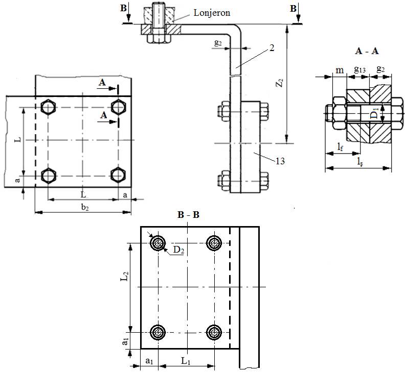
Constructive model
Constructive features and constraints
– for bracket 2, a flat-bar blank of width b2 = b13 (Ex.7.1) and thickness g2 may be adopted;
– the same hole positions, L and a, are adopted (Ex.7.1).
D. Calculation model, sizing and checking
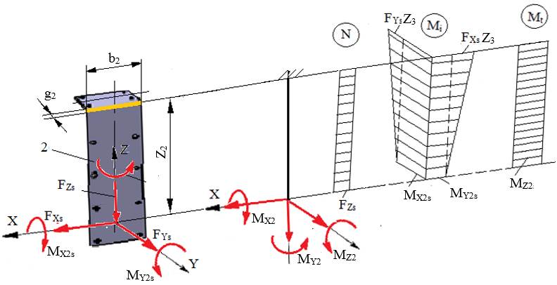
Calculation model
Calculation assumptions and loads
– the calculation model is a straight cantilever bar, loaded in tension by the force FZs; in oblique bending by the loads FXs, FYs and MX2s, MY2s; in torsion by the moment MZ2s; in shear by the forces FYs and FZs;
– elements 2/2′ are connected by clearance-fit bolted joints to elements 13/13′ on one side and to the side members of the vehicle chassis on the other;
– since a sizing model taking all loads into account is quite complex, a simplified model is adopted that considers the main bending load given by the force FYs and the moment MX2s.
Calculation data
– loading: FYs, MX2s;
– shape and dimensions: flat bar of width b2 = b13; the thickness g2 is unknown;
– materials: σ02 – the yield strength; c = 2…3 – the safety factor; σat = σ02/c – the allowable tensile stress; σaî = (1.05…1.1)σat – the allowable bending stress;
– bending moment in the critical section (simplified model): Mîmax = MX2s + FYs Z2.
Note. Since the external forces may act in either direction in service, the maximum possible load was determined (the moments were added in the relation).
Calculation relations
Bending strength condition in the critical section:
σîmax =  =
=  ≤ σaî.
Sizing
From the relation above, the required thickness is
 =
=  (Calc.8.1.1)
and from Annex.ST.01 a flat-bar blank of standard thickness g2 ≥ is adopted (the flat-bar width b2 = b13 was adopted in stage C).
E. Design of the constructive-technological shape
Constructive-technological drawing
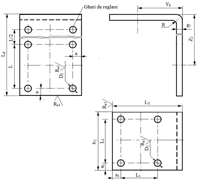
Recommendations for choosing the dimensions and constructive-technological parameters
– dimensions: Z2, YE, b2, g2, a, L; R = (1.5…3)g; LZ = Z2 + L/2 + a, LY = 2YE; a1 = (12…18) mm, L1 = LY − 2a1 − R; L2 = b2 − 2a1; the other dimensions (D1, D2) result from the calculation of the bolt-nut joints (Sec.8.2, Ex.8.2; Sec.8.4, Ex.8.4);
– the number of sets of adjustment holes is set when drawing the assembly;
– technological operations: milling, bending, drilling; fillet radius in the bending zone R = (1.5…3)g2;
– sharp edges are chamfered 1×45°;
– roughness of the surfaces machined by milling or drilling: Ra1 = 6.3 µm or Ra1 = 12.5 µm; Ra2 = 6.3 µm or Ra2 = 12.5 µm.