In the steps below, 🖱 means a left mouse click and → leads to the next action. Labels in the screenshots are those of the MDESIGN interface.
1. Loading diagram and input data
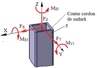
Loading diagram in the XYZ coordinate system of the ATD
Forces: FX = 1500 N, FY = 300 N, FZ = 700 N. Moments: MX5 = 25500 Nmm, MY5 = 183500 Nmm, MZ5 = 24000 Nmm. Geometric parameters: h5 = 50 mm, t5 = 5 mm; a = 3 mm. Material: S235, weldable general-purpose steel. Operating constraints: temperature T = (−30…40) °C. |
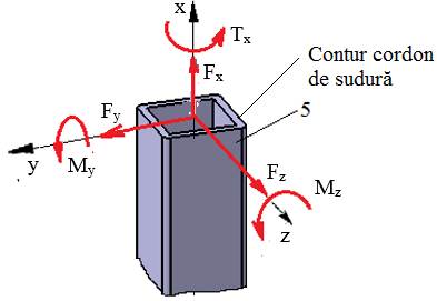
Loading diagram in the xyz coordinate system of MDESIGN
Forces and moments in the MDESIGN xyz coordinate system Forces: Fx = −FZ = −700 N, Fy = FX = 1500 N, Fz = FY = 300 N. Moments: Tx = MZ5 = 24000 Nmm, My = −MX5 = −25500 Nmm, Mz = MY5 = 183500 Nmm. |
2. Entering the data in MDESIGN (Annex.MD.2)
2.1 Launching the application
Opening the MDESIGN Weld Standard module
| 🖱 |  | → | 🖱 |  | → | 🖱 |  |
Resetting the data of the automatically loaded application
🖱 → [🖱 select the command
  ] → [🖱 select the option
  ].
].
Saving the application
🖱 (
( ,
,  ) →
) →  : [
: [ select the folder where the application will be saved],
[ enter the file name Welded joint 4-5], [
 :
:  ], 🖱
], 🖱
[the title of the main window shows:  ].
].
Opening the application (if it was created and saved earlier)
[select the folder where the application is saved] → 🖱 
Note. While working, save intermediate versions regularly for safety (the system may freeze), using 🖱 or F10.
2.2 Selecting the Input window and general settings
Selecting the language
[🖱 select from the list  the option
  ].
].
Selecting the Input page

Notes.
– the option  is selected to view the results obtained after solving;
– the option  is selected to view the input data.
General options (selected from the attached lists)

Notes.
– the option  means static strength analyses;
– the option  indicates that the assessment follows the DIN EN ISO 5017/2012 standard;
– the option  indicates that residual (internal) stresses are not taken into account.
2.3 Entering the geometric, technological, loading and material data
Entering the weld geometry (Geometry)
Choosing the type of weld ( )
)
🖱 (
( ) →
) →  : 🖱 select
  🖱
🖱 (the selected name appears automatically in the text box).
Note. The selection can also be made from the attached list.
Choosing the geometry of the beam section ( )
)
🖱 () → : 🖱 select  🖱 →
🖱 →  : 🖱 select from the list
  , 🖱 →
, 🖱 →  : 🖱 select from the list
  , 🖱 (the section data are filled in automatically in the grey boxes, which cannot be edited).
Note. The selection can also be started from the attached list.
Choosing the weld type ( )
)
[🖱 select from the list  (fillet weld)].
Choosing the type of weld bead ( )
)
[🖱 select from the list  (fillet weld)].
Entering the wall thickness of the welded element ( )
)
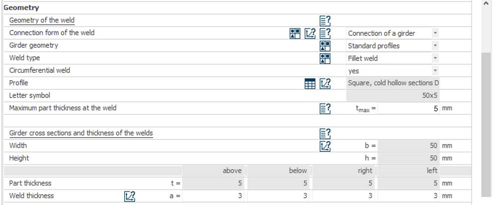
[enter the thickness in the box  , e.g. 4].
Entering the weld thicknesses ( )
)
[enter the thicknesses in the boxes  , e.g. 3/3/3/3].
Note. After the selections and entries above, the result is:
Entering the loading data (Loading data)
Entering the axial force ( )
)
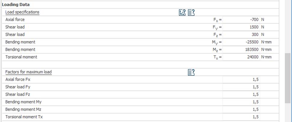
[enter the axial force in the box  , e.g. −700].
Entering the shear force ( )
)
[enter the shear force along the y axis in the box  , e.g. 1500].
Entering the shear force ( )
)
[enter the shear force along the z axis in the box  , e.g. 300].
Entering the bending moment ( )
)
[enter the bending moment about the y axis in the box  , e.g. −25500].
Entering the bending moment ()
[enter the bending moment about the z axis in the box  , e.g. 183500].
Entering the torsional moment ( )
)
[enter the torsional moment (about the x axis) in the box  , e.g. 24000].
Entering the maximum-load factors ( /
/ /
/ /
/ /
/ /
/ )
)
[enter the factor values in the corresponding boxes, e.g. 1.5/1.5/1.5/1.5/1.5/1.5].
Note. After the selections and entries above, the result is:
Entering the material data (Material Data)
Choosing the database ( )
)
[select from the list 🖱 (the MDESIGN database)].
Choosing the material type ( )
)
[select from the list 🖱 (steel)].
Choosing the material designation ( )
)
🖱 →
→  : [select the row with the material (
 )] 🖱
)] 🖱 (the material data are filled in automatically in the grey boxes, which cannot be edited).
Entering the material factor ( )
)
[enter the value in the corresponding box, e.g. 1.1].
Note. After the selections and entries above, the result is:
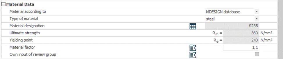
Meaning
Rm – ultimate strength; Re – yield point.
3. Solving the model and saving the results
| 🖱 |  | or 🖱 or F10 | → | Correct any inconsistencies or errors in the input data (only if warning windows appear) | → | 🖱 | or 🖱 or F10 | → 🖱 |  | → |   | Weld 4-5.pdf | → 🖱 |
4. Input data and results (Annex.MD.3.7_4-5)
Selecting the Output page

Geometry data
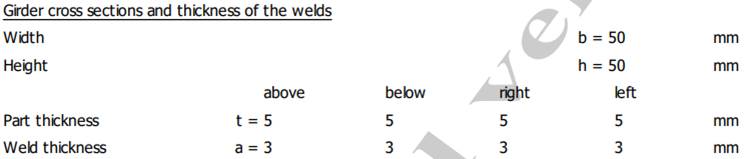
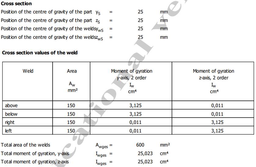
Meaning
– yS, zS – position of the centre of gravity of the part (beam section); ywS, zwS – position of the centre of gravity of the welds;
– Aw – area; Iw – second moment of area about the y/z axis; weld; above; below; right; left;
– Awges – total area of the welds; Iwges – total second moment of area about the y/z axis.
Loading data
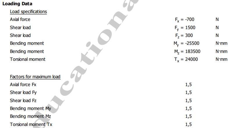
Meaning
– Load specifications – the loads in the section; Fx – axial force; Fy/Fz – shear loads; My/Mz – bending moments; Tx – torsional moment;
– Factors for max. load – the maximum-load factors.
Results obtained
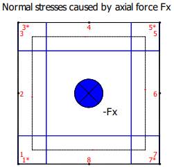
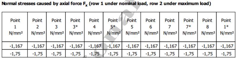
Normal stresses due to the axial force Fx (row 1 for the nominal force, row 2 for the maximum force)
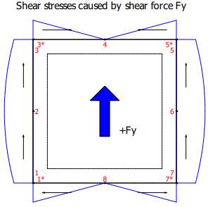
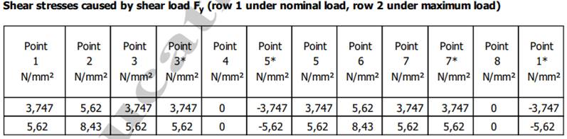
Shear stresses due to the shear force Fy (row 1 for the nominal force, row 2 for the maximum force)
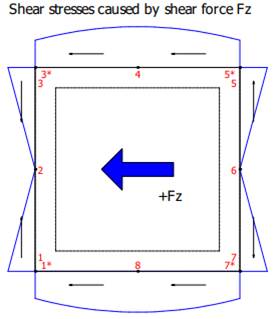
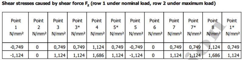
Stresses due to the shear force Fz (row 1 for the nominal force, row 2 for the maximum force)
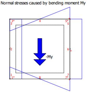
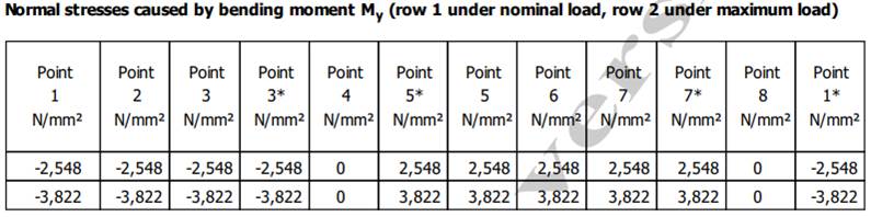
Normal stresses due to the bending moment My (row 1 for the nominal moment, row 2 for the maximum moment)
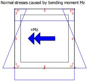
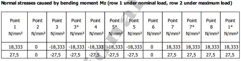
Normal stresses due to the bending moment Mz (row 1 for the nominal moment, row 2 for the maximum moment)
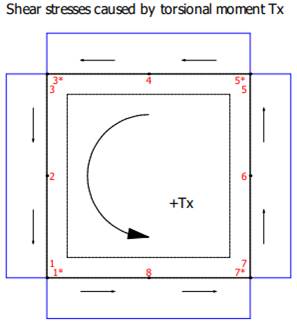
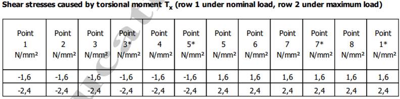
Shear stresses due to the torsional moment Tx (row 1 for the nominal moment, row 2 for the maximum moment)
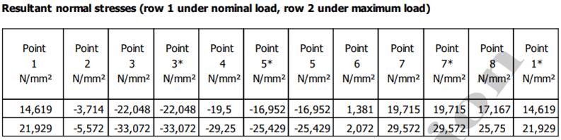
Resultant normal stresses (row 1 for the nominal loads, row 2 for the maximum loads)
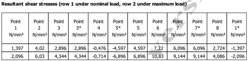
Resultant shear stresses (row 1 for the nominal loads, row 2 for the maximum loads)
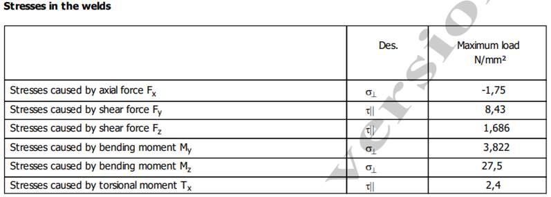
Maximum stresses in the weld for each type of load
Maximum and allowable stresses

Meaning
– Normal stresses caused by the axial force Fx; shear stresses caused by the shear force Fy; shear stresses caused by the shear force Fz; normal stresses caused by the bending moment My; normal stresses caused by the bending moment Mz; shear stresses caused by the torsional moment Tx;
– Resultant normal stresses (maximum); resultant shear stresses (maximum);
– σres – maximum resultant normal stress; τres – maximum resultant shear stress; σzul – allowable normal stress; τzul – allowable shear stress.
5. Checks
Strength check for normal stresses
σres ≤ σzul; 33.072 < 106.364 (satisfied).
Strength check for shear stresses
τres ≤ τzul; 10.83 < 106.364 (satisfied).