Launching the weld-checking module
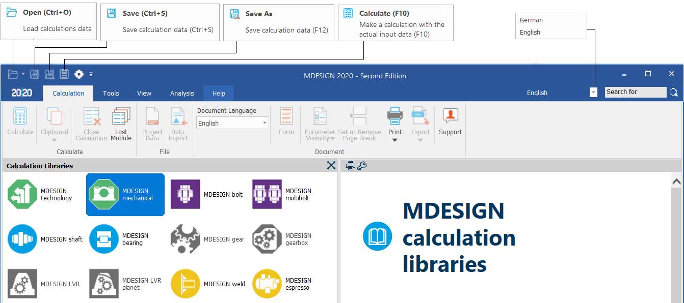
Main window of the MDESIGN package (Calculation Libraries)
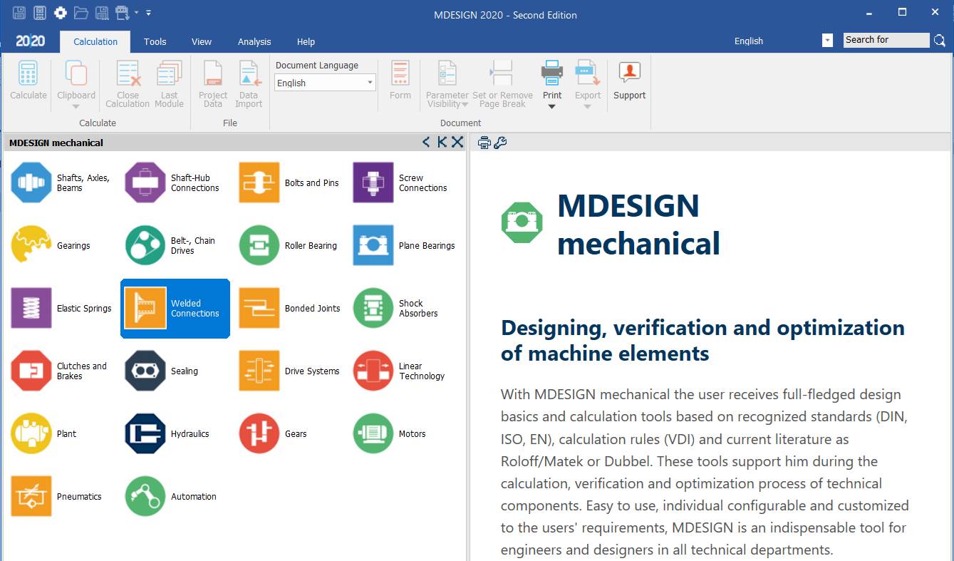
Main window of the MDESIGN mechanical group
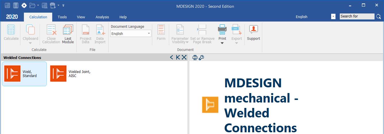
Main window of the Welded Connections group
Main window of the Weld, Standard module
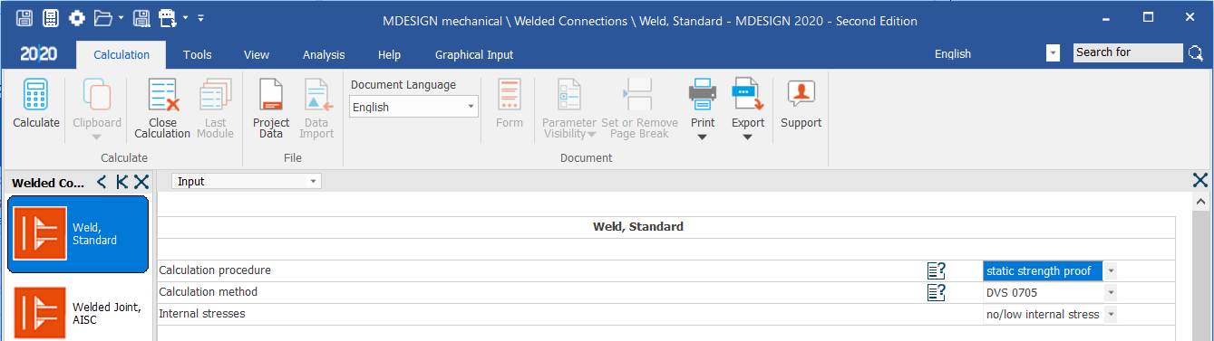
Input data page (Input)
General aspects
Selecting the Input page

Options
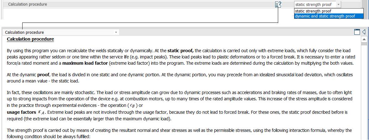
Calculation procedure
Meaning
– static strength proof; dynamic and static strength proof.
– Calculation procedure
The program calculates statically or dynamically loaded welds. For statically loaded welds, the calculation is made only for extreme loads, i.e. load peaks that occur rarely or only once in the life of the product (e.g. impact peaks). Such peaks (overloads) cause plastic deformation or forced fracture. The program needs the nominal force/moment and a maximum load factor; the extreme loads are obtained by multiplying the two.
For dynamically loaded welds, the load is split into a static and a dynamic part. The dynamic part can act as an ideal sinusoidal deviation oscillating about the mean value – the static load.
In reality these oscillations are mainly stochastic. The load or stress amplitude can increase through dynamic processes such as accelerating and braking masses, or light and heavy shocks in service, e.g. from an internal combustion engine running with variable-amplitude loads. In practice, according to experimental evidence, this is covered by an operating factor (cB) or application factor KA. Extreme load peaks are not covered by the operating factor, because they do not lead to forced fracture; for them the static check described above is needed (extreme loads may be larger than the dynamic loads).
The strength check determines the actual and allowable normal and shear stresses using theoretical relations.
Overload case

Meaning
Overload case: constant mean stress, Kappa = constant.
Meaning
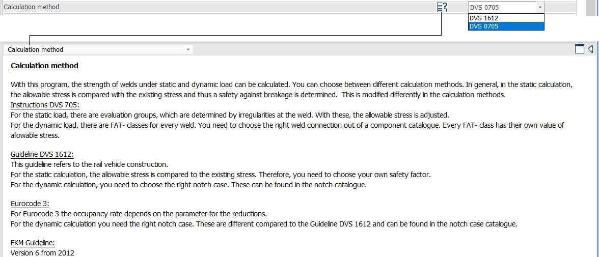
Calculation method
The program calculates weld strength under static and dynamic loading, with a choice of calculation methods. For the static calculation, the allowable and actual stresses are generally compared, giving a safety factor against failure; this procedure is adapted for each method.
Instructions DVS 705:
For static loads there are assessment groups, determined by the weld irregularities; the allowable stresses are adjusted accordingly.
For dynamic loads there are FAT classes for each weld; the welded joint of the component must be chosen from the catalogue, and each FAT class has its own allowable stress.
Guideline DVS 1612:
This guideline concerns rail vehicle construction.
For the static calculation, the allowable stresses are compared with the actual stresses, so a safety factor must be chosen.
For the dynamic calculation, the notch (stress concentrator) type must be chosen from the notch catalogue.
Weld geometry
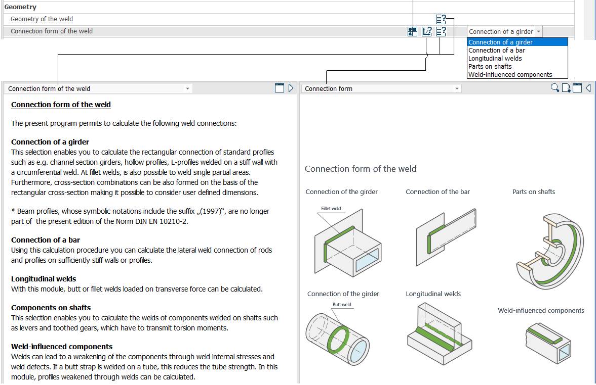
Forms of welded joints
Meaning
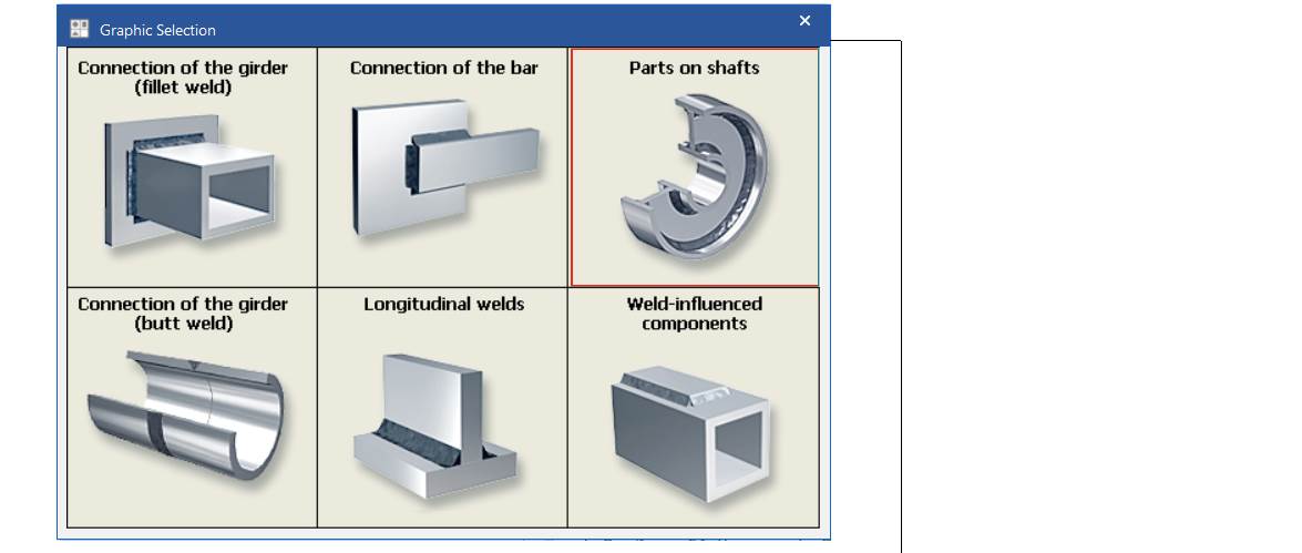
Connection form of the weld
The program can calculate the following welded joints:
Connection of girder; fillet weld; butt weld: a perpendicular connection of standard profiles (e.g. tubular girders, L-profiles) welded to a rigid wall along a circumferential contour. The fillet weld can be made over a single zone. Cross-section combinations with user-defined dimensions can also be formed.
Connection of bar: side welds of bars and profiles to walls or sufficiently rigid profiles.
Longitudinal welds: butt or fillet welds loaded by transverse forces.
Components of shafts: welded shaft components such as levers and gears that transmit torque.
Weld-influenced components: welds can weaken components through residual stresses and weld defects; e.g. welding a stiffener onto a tube reduces the tube's strength. Profiles weakened by welds can be calculated with this module.
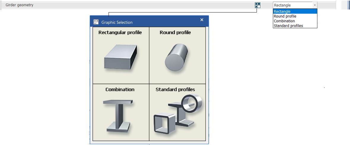
Beam geometry
Meaning
Rectangular profile; round profile; combination; standard profile.
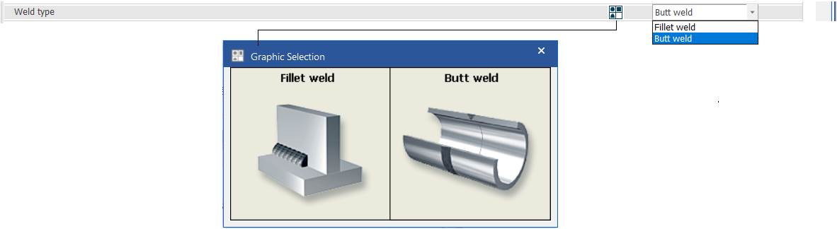
Weld type
Meaning
Fillet weld; butt weld.
Type of weld bead

Meaning
Circumferential weld (closed contour).
Wall thickness of the welded element
Meaning
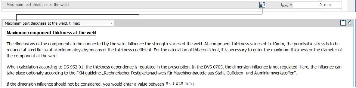
Maximum component thickness at the weld
The size of the welded elements influences the weld strength. For thick elements, t > 10 mm, the allowable stresses can be reduced by a thickness factor, for steels as for aluminium alloys. To calculate this factor, the thickness or diameter of the welded element must be entered.
If the size influence is not to be considered, enter a value 0 < t ≤ 10 mm.
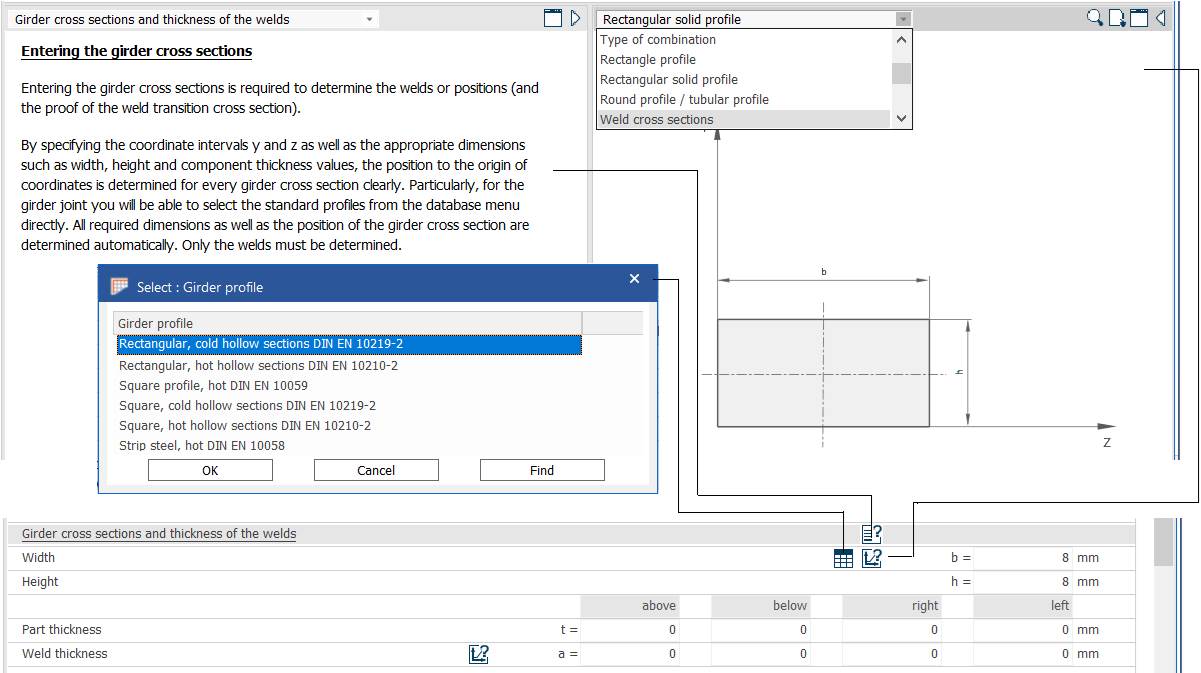
Girder cross-sections and weld thicknesses
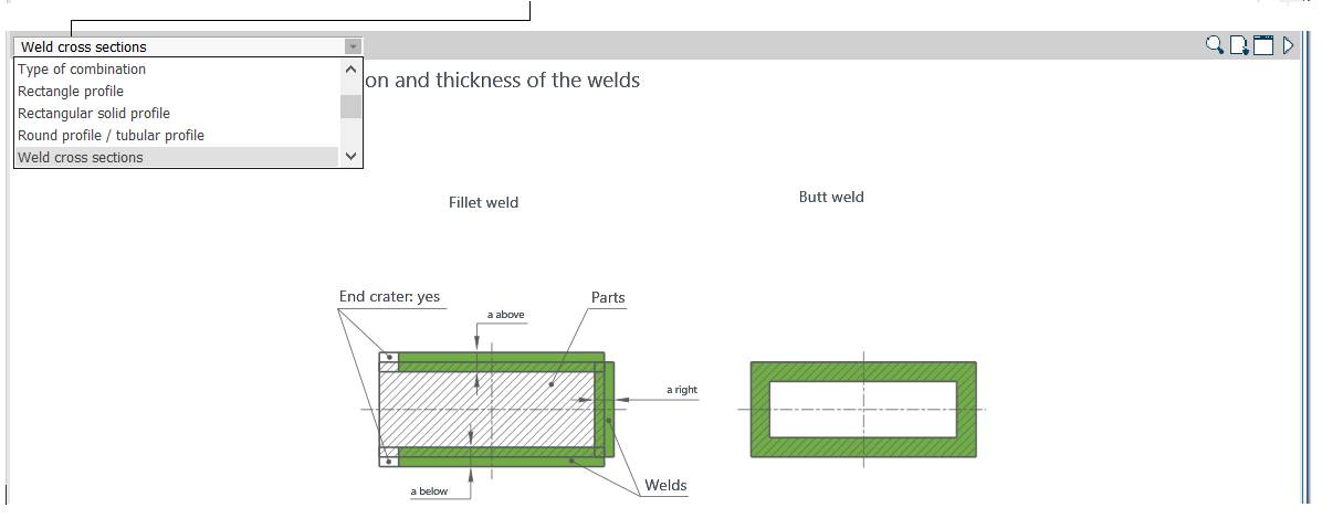
Meaning
Entering the girder cross-sections
The girder cross-sections are needed for the dimensions and positions of the welds (and for checking the transition zones between weld and cross-section).
By specifying the y and z coordinate ranges and the related dimensions (thickness, height, element thickness) relative to the coordinate origin, each girder cross-section is clearly defined. In particular, standard profiles can be selected directly from the database; all dimensions and the position of the cross-section are then determined automatically and only the weld has to be defined.
Girder profile: rectangular, cold-formed hollow sections DIN EN 10219-2; rectangular, hot-finished hollow sections DIN EN 10210-2; square profile, hot DIN EN 10059; square, cold-formed hollow sections DIN EN 10219-2; square, hot-finished hollow sections DIN EN 10210-2; strip steel, hot DIN EN 10058.
Loading data
Load specification
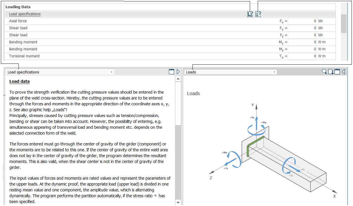
Meaning
Load data
For the strength check, the loads acting in the plane of the weld cross-section are entered as forces and moments along the x, y, z directions (see also the "loads" sketch).
Tension/compression, bending and shear stresses produced by these loads are considered, so transverse loads, bending moments etc. acting simultaneously can be entered, depending on the form of the welded joint.
Loads: the forces entered must be reduced to the centre of gravity of the girder, and the moments referred to it. If the centre of gravity of the weld area does not coincide with that of the girder, the program determines the resulting moments; the same applies when the shear centre is not at the girder centre.
The input forces and moments are nominal values and are parameters of the maximum loads. For the dynamic check (variable loading), the maximum load is split into a mean value and an alternating dynamic component; the program does this automatically if the stress ratio has been specified.
Axial force Fx; shear load Fy (along y); shear load Fz (along z); bending moment My (about y); bending moment Mz (about z); torsional moment Tx (about x).
Maximum load factors
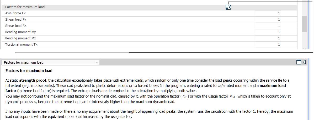
Meaning
Factors for max. load
In the static check, the calculation considers the maximum loads, i.e. load peaks that occur rarely or at least once during the whole service life (e.g. impulse or shock peaks), which cause plastic deformation or forced fracture. The program takes the nominal force/moment and a maximum load factor (extreme load factor); the maximum loads are obtained by multiplying the two.
The maximum load factor, or the load determined by it, should not be confused with the operating factor (cB) or application factor KA, which cover only dynamic processes, since extreme loads can be larger than the maximum dynamic load.
If no input indicates load peaks, the system uses the value 1 for this factor; the maximum load then equals the upper equivalent load increased by the application factor.
Material data
Options and type


Meaning
Material according to: MDESIGN database; own assignment (manual entry).
Type of material: steel, aluminium.
Selecting the material
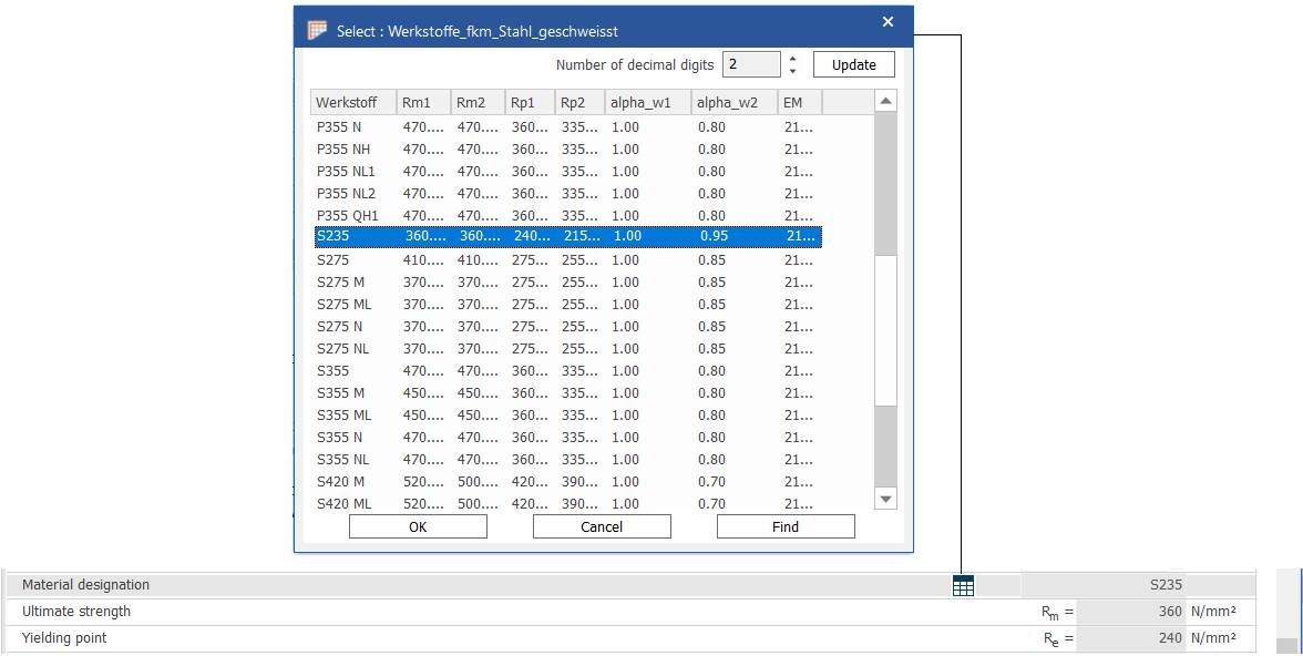
Meaning
Material designation: ultimate strength Rm; yield point Re.
Other material data
Meaning
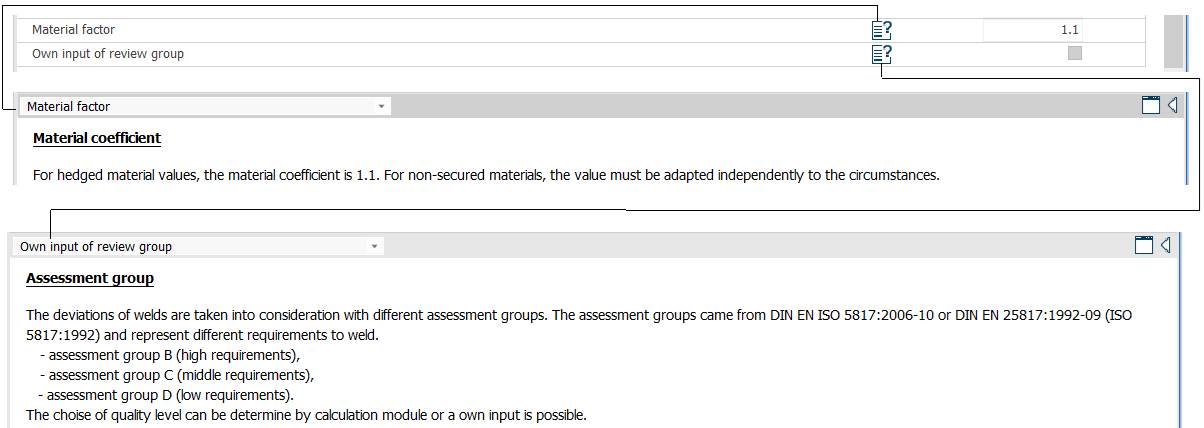
Material coefficient: to cover material risks, the material coefficient is 1.1; for uncertain materials the value is set separately according to the circumstances.
Assessment group: weld imperfections are taken into account through assessment groups, given in DIN EN ISO 5817:2016 or DIN EN 25817:1992 (ISO 5817:1992), which set different requirements for welds:
– assessment group B (high requirements);
– assessment group C (medium requirements);
– assessment group D (low requirements).
The quality level can be determined by the calculation module or entered as input.