A. Loading diagram and design data
Loading diagram
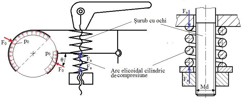
Design data
Preload pressure of the spherical pair: p0 = (0.1…0.2) pmax, where pmax is the maximum pressure in the spherical pair under load (Ex.8.5).
Spring preload force
With r = Ds/2 and Fr = F0, the pressure relation from Annex.8.5.1 becomes
p0 =  =
=  ,
,
from which
F0 =  (Calc.8.6.1),
where Ds is the diameter of the coupling ball.
Spring assembly force
Fa = F0 sin θ (Calc.8.6.2),
where θ = 35°…45°.
Dimensions: the diameter of the threaded shank of the eye bolt, Md (metric thread), may be M8, M10 or M12; spring stroke between the coupled and uncoupled positions h = 6…10 mm.
Operating constraints: temperature T = (−30…40) °C; outdoor working environment with high humidity.
Design constraints: interchangeability with the coupling systems in use in the EU.
Note. The cylindrical helical compression spring preloads the spherical pair with the pressure p0, to eliminate any play that could appear in service (especially when switching from pulling to pushing the trailer).
B. Choice of material and heat treatments
The helical spring is made of special spring steel (Annex.M.01; Annex.M.02).
Material properties
| Material | Heat treatments | Ultimate tensile strength |
|---|---|---|
| Special spring steel | Annealing, quenching and tempering | σr = (1400…1800) MPa |
Heat treatments
Annealing at (650…700) °C before forming.
Quenching at (820…870) °C with oil cooling and tempering at (550…650) °C, HRC 45…55, after forming (coiling into the helical shape).
C. Design of the constructive shape
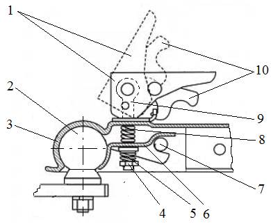
Structure of the assembly
Key: 1 – coupling/uncoupling handle; 2 – towing hook; 3 – towing coupling body; 4 – nut; 5 – cylindrical helical preload spring; 6 – clamp; 7 – pin joint; 8 – spring returning the clamp to the uncoupled position; 9 – eye bolt; 10 – self-locking latch. |
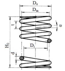
Structure and dimensional parameters of the cylindrical helical compression spring
Key: d – wire diameter; Dm – mean diameter; De – outer diameter; Di – inner diameter; t – pitch; H0 – free length of the spring; α – helix angle. |
D. Calculation models, sizing and checking
Strength calculation model
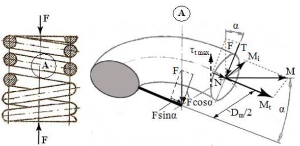
Key: F – spring load; α – helix angle; T – shear force; Mt – torsional moment; Mî – bending moment; N – axial force; τmax – maximum shear stress.
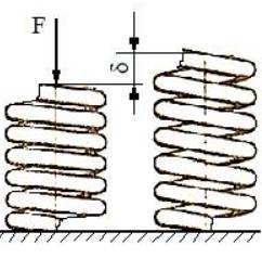
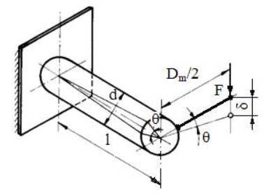
Deformation calculation model (displacement, deflection, stroke) and spring characteristic
Deformation calculation model (displacement, deflection, stroke)
Key: F – spring load; δ – spring deflection; d – wire diameter; θ – angle of twist of the simplified straight-bar model; Dm – mean diameter of the spring. |
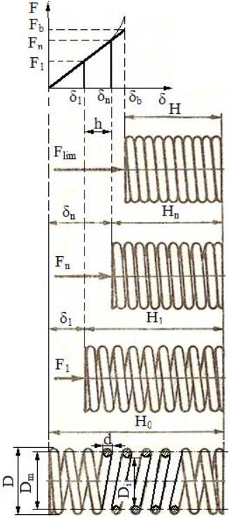
Spring characteristic
|
Key (spring characteristic): F1 – assembly force; Fn – maximum (nominal) force; Flim – force at solid length; δ1 – assembly deflection; δn – maximum (nominal) deflection; δb – deflection at solid length; H0 – free (unloaded) length; H1 – length under F1; Hn – length under Fn; H – solid length. | |
Calculation assumptions and loads
– since the helix angle is small, α = 6…9°, sin α ≈ 0 and cos α ≈ 1 are assumed, so the shear, compression/tension and bending stresses are neglected;
– the main load on the coil is torsion.
Calculation data
– loading: Fn = Fa – the maximum (nominal) force; F1 = (0.1…0.2) Fn – the assembly force;
– dimensions: the mean diameter of the spring Dm = (1.4…1.6) Md, where Md may be M8, M10 or M12; spring stroke h = 6…10 mm;
– materials: the allowable stress τa (Annex.M.02); G = 8.5·104 MPa – the shear modulus of the spring material.
Calculation relations
– torsional strength condition of the spring coil (strength model):
τtmax = K  ≤ τa,
≤ τa,
where K = 1.05…1.2 is the stress concentration factor for torsional shear;
– spring deflection under the load Fn:
δn =  ,
,
where n is the number of active coils and G the shear modulus of the spring material;
– spring stroke:
h = 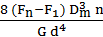 ,
,
where d is the wire diameter.
Sizing
Wire diameter
From the torsional strength condition (see above), the required wire diameter is
dnec =  (Calc.8.6.3).
A wire diameter d ≥ dnec is adopted from the standard spring-steel wire diameters {… 1.0; 1.2; 1.3; 1.4; 1.5; 1.7; 1.8; 1.9; 2.0; 2.5; 3.0; 3.5; 4.0; 4.5; 5 …} mm.
Number of active coils
From the stroke relation (see above), the required number of active coils is
nnec = 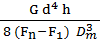 (Calc.8.6.4).
The number of active coils n ≥ nnec is adopted, rounded up.
Other dimensional parameters
– number of end (seating) coils nr = 1.5;
– total number of coils nt = n + nr;
– pitch of the free (unloaded) spring:
t = d +  + 0.1d = 1.1d +
  (Calc.8.6.5);
– free length of the spring H0 = n·t + nr d (Calc.0);
– length of the spring under the assembly force F1 and under the nominal force Fn:
H1 = H0 − δ1 = H0 −  (Calc.8.6.6),
Hn = H0 − δn = H0 − (Calc.8.6.6);
– spring stroke h = H1 − Hn (Calc.0);
– blank length (wire length before coiling):
ls = 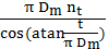 (Calc.8.6.7).
Nut tightening torque (applied with the wrench)
– parameters of the joint elements: from Annex.ST.03, the thread dimensions (Md), d, d2, p; matching the thread size (Md), the clearance hole diameter D1 (medium series) is taken from Annex.ST.05;
– thread torque (friction in the thread):
Mî = Fst  tan(arctan
  + arctan
  ) (Calc.3.3.4),
where Fst = F1, µ = 0.15…0.25 is the friction coefficient in the thread, α = 60° the profile angle of the metric thread and p the thread pitch;
– friction torque between nut and washer:
Mp = Fst  μ2
μ2  (Calc.3.3.5),
where µ2 = 0.15…0.25 is the friction coefficient between nut and washer and D1 the clearance hole diameter;
– nut tightening torque (applied with the wrench):
Mc = Mî + Mp (Calc.0),
which tightens the threaded joint and therefore compresses the spring with the assembly force F1.
E. Design of the constructive-technological shape
Constructive-technological drawing (including the spring characteristic)
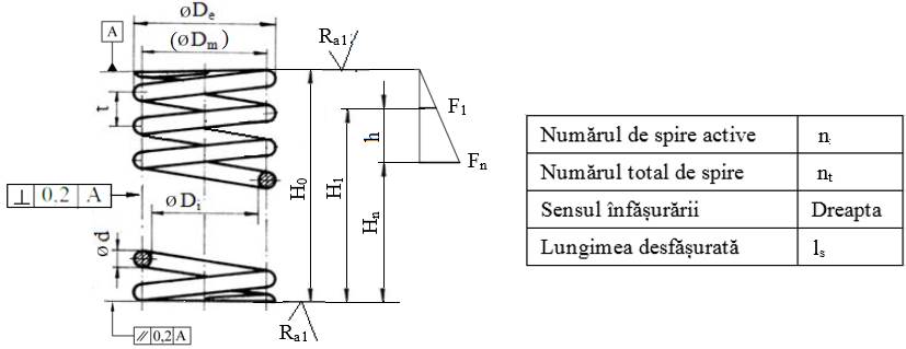
Recommendations for choosing the dimensions and constructive-technological parameters
– geometric parameters: d, t, Di, Dm, De, n, nt, H0;
– parameters of the elastic characteristic: H1, Hn, h, F1, Fn;
– the seating faces are ground after heat treatment to a roughness Ra1 = 1.6 μm or Ra1 = 3.2 μm; perpendicularity and parallelism tolerances must be ensured;
– when checking the elastic characteristic, force tolerances of ±10 N are considered.
Recommendations for choosing the dimensions of the threaded joint elements (bolt-nut):
– eye bolt with thread size Md, d;
– hexagon nut (Annex.ST.04): Md, S, m;
– plain washer (Annex.ST.06): d, d1, d2, h;
– Grower spring washer (Annex.ST.07): MN, d, d1, d2, g.