A. Loading diagram and design data
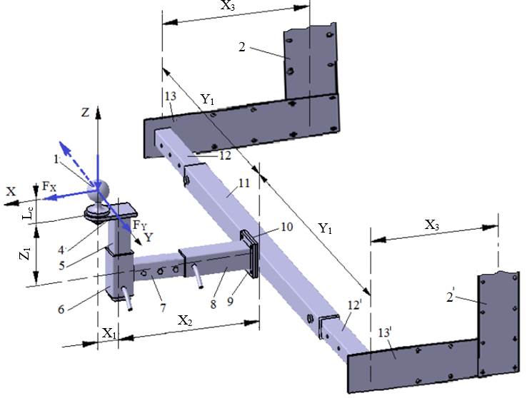
External loading diagram
|
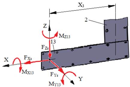
Loading diagram of element 13/13′ |
 |
Design data
External forces: FX, FY, FZ act at distances Lc (Ex.3.1), X1, X2, X3, Y1, Z1 (Ex.1.2.2); the forces and moments at the centre of the welded joint are calculated (Calc.0):
FXs = FXd = FX/2,
FYs = FYd = FY/2,
FZs = FZd = FZ/2;
MX13 = FY (Lc + Z1)/2,
MY13 = FX (Lc + Z1)/2 + FZ (X1 + X2)/2,
MZ13 = FX Y1/2 + FY (X1 + X2)/2.
Note. Since the external forces may act in either direction in service, the maximum possible loads were determined (the components were added in the moment relations).
Dimensional constraints: the square tube 12, with dimensions h12, t12 (Ex.6.1), will be welded to tie rod 13.
Operating constraints: temperature T = (−30…40) °C; outdoor working environment with high humidity.
Design constraints: weldable materials.
B. Choice of material and heat treatment
Since elements 13 (13′) are welded parts, a weldable steel is adopted (e.g. S185, S235, S275) according to SR EN 10025-2 (STAS 500/2) (Annex.M.01). These steels are not heat-treated before welding; after welding, the subassembly may undergo stress-relief annealing. For the adopted steel, the yield strength σ02 and the ultimate tensile strength σr are retained for the calculations.
C. Design of the constructive shape
Constructive model
|
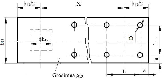
Constructive features and constraints – the square tube 12 is T-welded onto tie rod 13; – starting from the outer envelope of the weld contour, and allowing room for the bolt head together with the wrench, the width b13 = h12 + (60…80) mm is adopted; a flat bar of standard width b13 is recommended (Annex.ST.01). |
D. Calculation model, sizing and checking
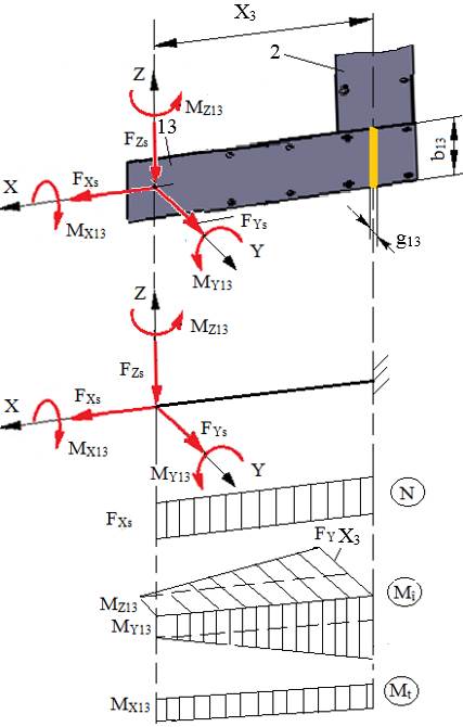
Calculation model
|
Calculation assumptions and loads – the calculation model is a straight cantilever bar, loaded in tension by the force FXs; in oblique bending by the loads FZs, FYs and MZ13, MY13; in torsion by the moment MX13; in shear by the forces FYs and FZs; – elements 13/13′ and 2/2′ are connected by bolted joints with clearance-fit bolts; – since a sizing model taking all loads into account is quite complex, a simplified model is adopted that considers the main bending load given by the force FYs and the moment MZ13. Calculation data – loading: FYs, MZ13; – shape and dimensions: flat bar with dimensions b13, X3 + b13; the thickness g13 is unknown; – materials: σ02 – the yield strength; σat = σ02/c – the allowable tensile stress, c = 2…3 – the safety factor; σaî = (1.05…1.1)σat – the allowable bending stress; – bending moment in the critical section (simplified model): Mîmax = MZ13 + FYs X3. Calculation relations – bending strength condition in the critical section: σîmax = – sizing: from the relation above, the required thickness is
and from Annex.ST.01 a flat-bar blank of standard thickness g13 ≥ |
 =
=  ≤ σaî;
 =
=  (
(E. Design of the constructive-technological shape
Constructive-technological drawing
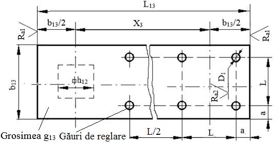
Recommendations for choosing the dimensions and constructive-technological parameters:
– dimensions: b13, g13, L13 = X3 + b13; a = (12…18) mm, L = b13 − 2a; the clearance hole diameter D1 results from the calculation of the bolted joint (Sec.8.2, Ex.8.2);
– the number of sets of adjustment holes is set when drawing the assembly;
– technological operations: milling the ends and drilling;
– sharp edges are chamfered 1×45°;
– roughness of the surfaces machined by milling or drilling: Ra1 = 6.3 µm or Ra1 = 12.5 µm; Ra2 = 6.3 µm or Ra2 = 12.5 µm.