In the steps below, 🖱 means a left mouse click and → leads to the next action. Labels in the screenshots are those of the MDESIGN interface.
1. Loading diagram and input data
External loading diagram and geometric parameters
|
Input data (Ex.6.7) Geometric parameters h11 = 60 mm, t11 = 5 mm, h12 = 50 mm, t12 = 5 mm, Db = 8 mm. External force FY = 300 N; FYs = FY/2 = 150 N. Operating conditions Temperature T = −30 °C…40 °C; outdoor working environment with high humidity. Design constraints The pin is made of structural steel E295. |
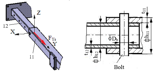
2. Entering the data in MDESIGN (Annex.MD.3)
2.1 Launching the application
Opening the module (pin connection)
| 🖱 |  | → | 🖱 |  | → | 🖱 |  |
Resetting the data of the automatically loaded application
🖱 → [🖱 select the command
  ] → [🖱 select the option
  ].
].
Saving the application
🖱 (
( ,
,  ) →
) →  : [
: [ select the folder where the application will be saved], [
 enter the file name Pin joint 11-12], [
 :
:  ], 🖱
], 🖱 [the title of the main window shows:
  ].
].
Opening the application (if it was created and saved earlier)
[select the folder where the application is saved] → 🖱
Note. While working, save intermediate versions regularly for safety (the system may freeze), using 🖱 or F10.
2.2 Selecting the Input window and general settings
Selecting the Input page

Notes.
– the option  is selected to view the results obtained after solving (calculation, see section 4);
– the option  is selected to view the input data (see the next subsection).
2.3 Entering the geometric, technological, loading and material data
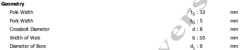
Entering the joint geometry (Geometry)
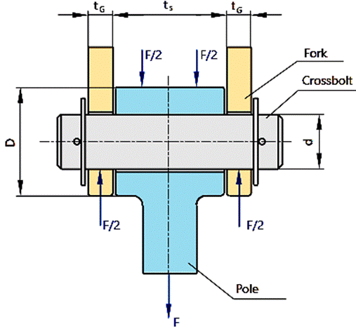
Geometry of the pin joint in MDESIGN
Meaning
Crossbolt – the transverse pin; Fork – the fork (clevis); Pole – the rod; d – pin diameter; tG – thickness of the fork cheek; tS – thickness of the rod; D – width (diameter) of the rod; F – the force loading the rod.
Entering the rod thickness ( )
)
[enter the rod thickness (2t12) in the box  , e.g. 10].
Entering the fork thickness ( )
)
[enter the fork thickness (t11) in the box  , e.g. 5].
Entering the pin diameter ( )
)
[enter the pin diameter (Db) in the box  , e.g. 8].
Entering the rod width ( )
)
[enter the value in the box  , e.g. 50].
Entering the bore diameter ( )
)
[enter the diameter in the box  , e.g. 10].
Note. After the selections and entries above, the result is:

Entering the loading data (Loading data)
Choosing the type of loading ( )
)
[select the option  ].
].
Entering the operating factor ( )
)
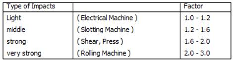
[enter the impact factor in the box 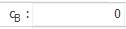 , e.g. 1.4 for medium (middle) impact, see the following table].
Entering the force on the rod ( )
)
[enter the force in the box 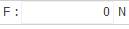 (F = FYs, e.g. 150)].
Note. After the selections and entries above, the result is:

Entering the material data (Material Data)
Choosing the pin material
[select from the list  , 🖱
, 🖱 (the MDESIGN database)].
[select from the list  , 🖱
, 🖱  ].
].
Choosing the material designation ( )
)
🖱 →
→  : [select the row with the material (
 )] 🖱
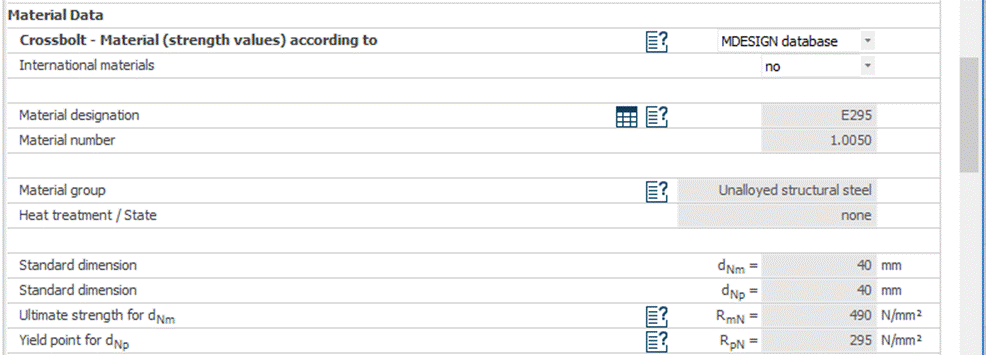
)] 🖱 (the material data are filled in automatically in the grey boxes, which cannot be edited).
Note. After the selections and entries above, the result is:
Entering the working temperature ( )
)
[enter the value in the box  , e.g. 40].
Entering the semi-finished product option ( )
)
[select from the list , 🖱 ].
Note. After the selections and entries above, the result is:

Choosing the rod material
[select from the list  , 🖱 (the MDESIGN database)].
[select from the list , 🖱  ].
].
Choosing the material designation ()
🖱 → : [select the row with the material ( )] 🖱
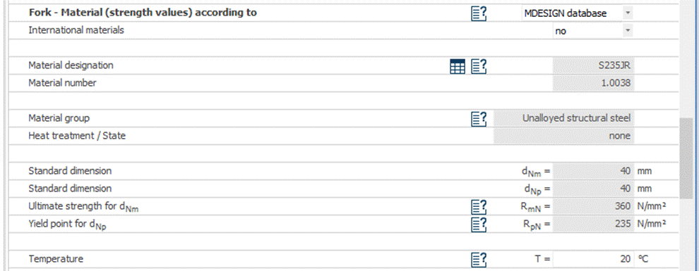
)] 🖱 (the material data are filled in automatically in the grey boxes, which cannot be edited).
Note. After the selections and entries above, the result is:
Entering the working temperature ()
[enter the value in the box , e.g. 40].
Entering the semi-finished product option ( )
)
[select from the list , 🖱 ].
Note. After the selections and entries above, the result is:

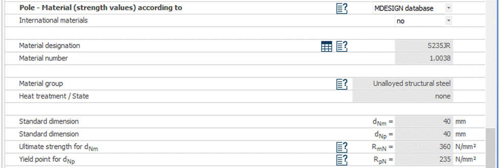
Choosing the fork material
[select from the list  , 🖱 (the MDESIGN database)].
[select from the list , 🖱 ].
Choosing the material designation ( )
)
🖱 → : [select the row with the material (
 )] 🖱
)] 🖱 (the material data are filled in automatically in the grey boxes, which cannot be edited).
Note. After the selections and entries above, the result is:
Entering the working temperature ( )
)
[enter the value in the box  , e.g. 40].
Entering the semi-finished product option ( )
)
[select from the list , 🖱 ].
Note. After the selections and entries above, the result is:

Meaning
T – Temperature (maximum working temperature); Material, surface hardened; Loads mainly crosswise to the preferred direction of machining (rolling).
3. Solving the model and saving the results
| 🖱 |  | or 🖱 or F10 | → | Correct any inconsistencies or errors in the input data (only if warning windows appear) | → | 🖱 | or 🖱 or F10 | → 🖱 |  | → |   | Pin joint 11-12.pdf | → 🖱 |
4. Results and checks
4.1 Results (Annex.MD.6.8_11-12)
Selecting the Output page

Input data
Geometry data
Loading data

Pin material data

Fork material data

Rod material data

Results
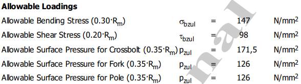
Strengths and allowable stresses (pressures)

Meaning
– Material Data: Rm – ultimate strength of the material for the pin (Crossbolt) / the fork (Fork) / the rod (Pole); Re – yield strength of the rod material (for Pole).
– Allowable Loadings: σbzul – allowable bending stress; τvorth – allowable shear stress; pzul – allowable surface pressure for the pin (Crossbolt) / the fork (Fork) / the rod (Pole).
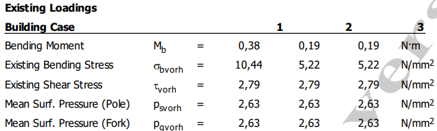
Actual stresses
Meaning
– Building Case (design case)
 | Design case 1: pin – fork = clearance fit; pin – rod = clearance fit |
 | Design case 2: pin – fork = press fit; pin – rod = clearance fit |
 | Design case 3: pin – fork = clearance fit; pin – rod = press fit |
– Mb – bending moment; σbvorth – existing (actual) bending stress; τvorth – existing shear stress; psvorth – mean surface pressure between pin and rod (Mean Surf. Pressure (Pole)); pvorth – mean surface pressure between pin and fork (Mean Surf. Pressure (Fork)).
Actual safety factors
Meaning
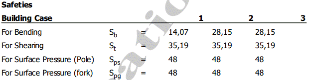
– Safeties (safety factors), Building Case (design case), see above.
– Sb – safety factor for bending; St – safety factor for shearing; Sps – safety factor for the surface pressure on the rod (Pole); Spg – safety factor for the surface pressure on the fork.
General data on the stresses in the rod body

Meaning
σw – maximum normal stress in the rod near the pin (Max. Normal Stress); σwzul – allowable normal stress of the rod material (Allowable Normal).
4.2 Checks
The pin joint of tubes 11 and 12 falls under design case 1
 | Design case 1: pin – fork = clearance fit; pin – rod = clearance fit |
Bending strength of the pin
σbvorh ≤ σbzul; 10.44 < 147 MPa (satisfied),
or
Sb ≥ Sadm; 14.07 > 2 (satisfied).
Shear strength of the pin
τvorh ≤ τbzul; 10.44 < 98 (satisfied),
or
St ≥ Sadm; 35.19 > 2 (satisfied).
Crushing strength in the pin–rod contact
psvorh ≤ pzul; 2.63 < 126 (satisfied),
or
Sps ≥ Sadm; 48 > 2 (satisfied).
Pin–fork contact
psvorh ≤ pzul; 2.63 < 126 (satisfied),
or
Spg ≥ Sadm; 48 > 2 (satisfied).
Note. Sadm is the allowable safety factor (Sadm = 2 was adopted).
Checking the rod
σw ≤ σwzul; 2.39 < 117.5 (satisfied).