Launching the pin-joint checking module
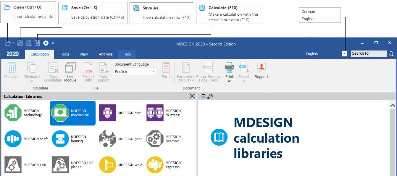
Main window of the MDESIGN package (Calculation Libraries)
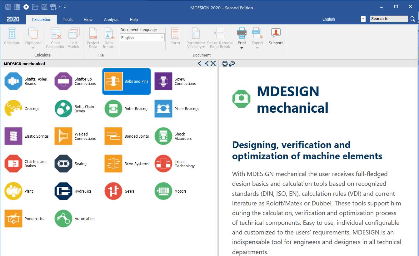
Main window of the MDESIGN mechanical group
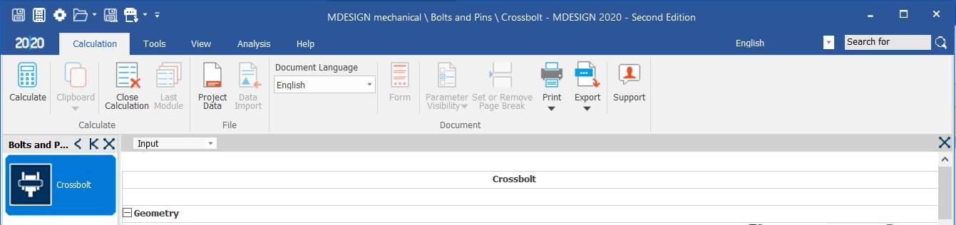
Main window of the Bolts and Pins group

Main window of the Crossbolt module
Input data page (Input)
General aspects
Selecting the Input page

Calculation principles
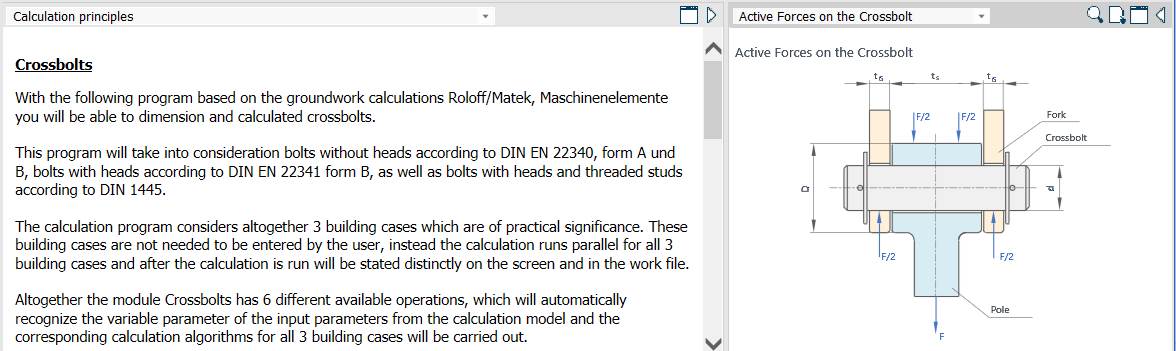
Meaning
– Active forces on the crossbolt: pole (rod); fork.
– Crossbolts
The program, based on the calculations in Roloff/Matek, Machine Elements (also available in Romanian translation), sizes and calculates crossbolts (transverse pins).
It covers headless pins according to DIN EN 22340, forms A and B, headed pins according to DIN EN 22341, form B, and headed pins with a threaded portion according to DIN 145.
The program considers together the three design cases that often occur in practice. These do not have to be entered by the user: the calculations run in parallel for all 3 cases and are then shown separately on screen and in the output file.
The Crossbolt module also has 6 distinct operating modes, which automatically recognise the variable input parameters of the calculation model and apply the corresponding algorithms for all 3 design cases.
The 3 design cases are:
Case 1: pin–fork, interference fit; pin–pole, interference fit.
Case 2: pin–fork, interference fit; pin–pole, clearance fit.
Case 3: pin–fork, clearance fit; pin–pole, interference fit.
Joint geometry
Pole width, fork width and pin diameter
Meaning
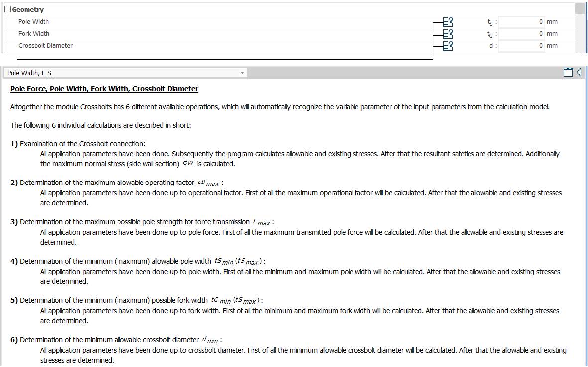
– Pole force, pole width, fork width, crossbolt diameter
The six calculation modes, recognised automatically from the variable inputs, are:
– Checking the crossbolt joint: all parameters are given; the program calculates all actual stresses and then the safety results; in addition, the maximum normal stress (in the section) σw is calculated.
– Determining the maximum operating factor cBmax: all other parameters are given; the maximum operating factor is calculated first, then all allowable and actual stresses.
– Determining the load capacity of the pole for the transmitted force Fmax: all other parameters are given; the maximum transmitted force is calculated first, then all actual stresses.
– Determining the minimum (maximum) pole thickness tSmin (tSmax): all other parameters are given; the minimum and maximum pole thicknesses are calculated first, then all actual stresses.
– Determining the minimum (maximum) fork thickness tGmin (tGmax): all other parameters are given; the minimum and maximum fork thicknesses are calculated first, then all actual stresses.
– Determining the minimum pin diameter dmin: all other parameters are given; the pin diameter is calculated first, then all allowable and actual stresses.
Web width, bore diameter
Meaning
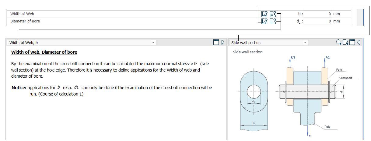
– Width of web, diameter of bore
When checking the crossbolt joint, the normal stress σw in the wall of the pole/fork at the hole can be calculated; for this, the pole/fork width and the hole diameter must be entered.
Note: b and dL are entered according to the calculation models adopted.
Loading type
Meaning
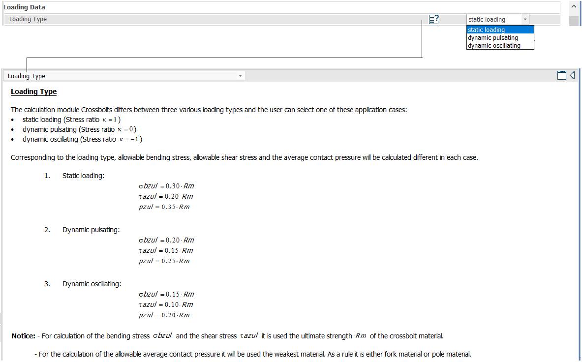
– Loading type
The calculation differs for the 3 loading types; the user selects one of:
– static loading (stress ratio k = 1);
– pulsating (repeated) loading (stress ratio k = 0);
– alternating (fully reversed) loading (stress ratio k = −1).
According to the loading type, the allowable bending stress (σbzul), allowable shear stress (τazul) and allowable mean contact pressure (pzul) are calculated differently for each case.
Notes:
– the allowable bending stress σbzul and the allowable shear stress τazul are calculated from the ultimate strength of the pin material;
– the allowable mean contact pressure is calculated from the ultimate strength of the weaker material; this applies both to the pole contact zone and to the fork contact zones.
Operating factor and pole force
Meaning
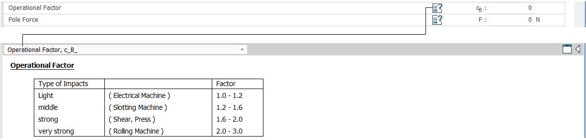
– Operational factor
Type of impacts: light (electrical machines); medium (slotting machines); strong (shears, presses); very strong (rolling mills).
Material data
Choosing the pin material
Meaning
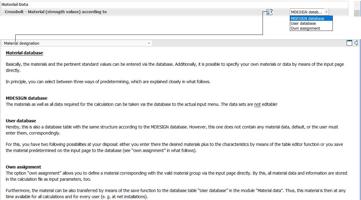
Crossbolt – material (strength values) according to: MDESIGN database; user database; own assignment.
– Material database: the easiest way is to take materials and standard values from the database; own materials or data can also be entered directly on the input page, in one of three ways:
MDESIGN Database: the materials and data needed for the calculation are taken from the database through the input menu; the selected data cannot be edited.
User Database: a database table with the same structure as the MDESIGN database, initially empty; the user either enters any material and its properties in an editable table, or saves a material defined on the input page into it (see "Own assignment" below).
Own assignment: the properties of a material are defined as a separate group on the input page, so all material information is stored in the calculation file as input parameters. The material group can also be transferred with the save function into the "User database" table of the "Material data" module, making it available at any time for all calculations and users (e.g. network installations).

Selecting the material

Meaning
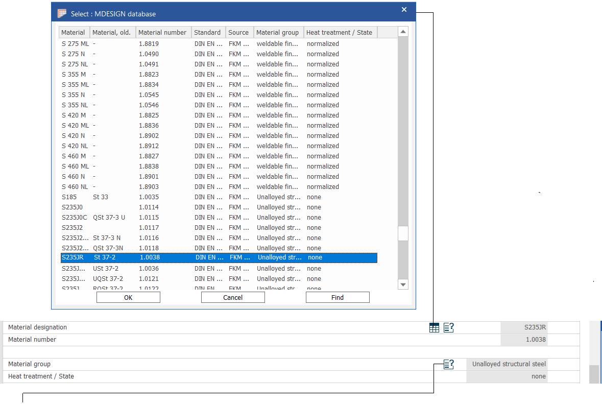
Material designation.
Material group / heat treatment or state: besides documentation, this assigns the technological size factor, the fatigue limit factor, the temperature factor and the material group.
Material data

Meaning
– Ultimate strength for…
– Material standard values: the standard values of the ultimate strength RmN and the yield strength RpN correspond to standard reference sizes, represented by an equivalent diameter dmN or dpN.
Note: "yield point" is used as a general term for the yield strength and the 0.2% proof stress.
Entering the temperature
Meaning
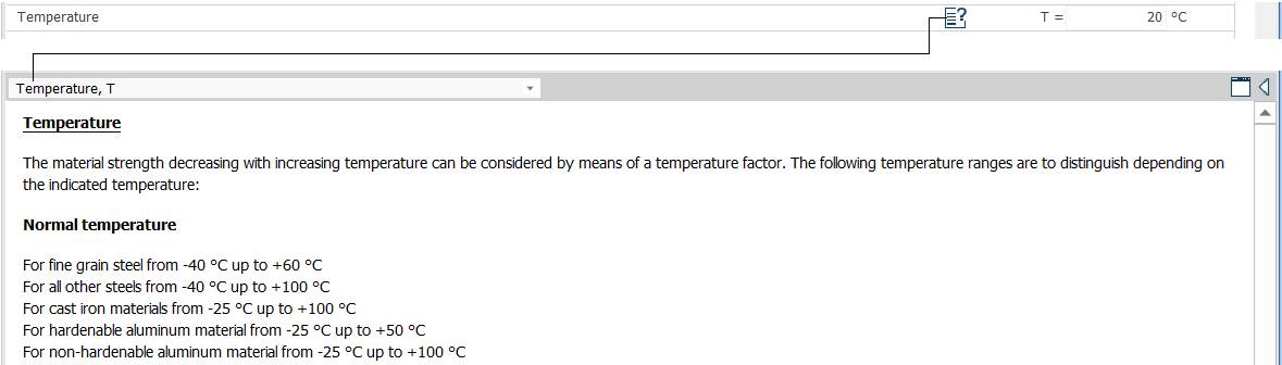
– Temperature
The decrease of material strength with increasing temperature can be taken into account by a temperature factor. Depending on the temperature entered, the following ranges are distinguished:
Normal temperature
Fine-grained steels: −40 °C to 60 °C.
Other steels: −40 °C to 100 °C.
Brittle materials: −25 °C to 100 °C.
Duralumin: −25 °C to 50 °C.
Soft aluminium alloys: −25 °C to 100 °C.
Other material data

Meaning
– Material, surface hardened.
– Material with hard boundary layer: plastic deformation of surface-hardened components, especially at stress concentrators, is limited by the surface hardness and may lead to unacceptable surface cracks; therefore the plastic deformation factor is not used in the design calculation and npl = 1 is taken.
If there is no hard surface layer (option "no"), the program sets the plastic deformation factor automatically according to the heat treatment and uses it in the subsequent calculations.

Meaning
– Loads mainly crosswise to the preferred direction of working (rolling).
– Considering the direction of rolling: strength values depend on the preferred working direction of the blank (rolling, forging) relative to the stress. If the material has reduced strength across that direction, entering "yes" applies the anisotropy factor kA.
For all brittle materials the anisotropy factor is generally not used, i.e. kA = 1.
Choosing the fork and pole materials


Meaning
Fork – material (strength values) according to: …
Pole – material (strength values) according to: …
Note. The other meanings are the same as for the pin (crossbolt) material described above.