Diagram of the towing device mounted and coupled to the trailer
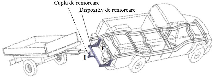
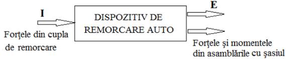
Notation: I – input, E – output
Note. The towing device must keep the drawbar of a single-axle trailer in a horizontal position.
Views and mounting diagrams
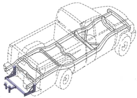
View of the towing device with high-mounted hook (ATDs)
|
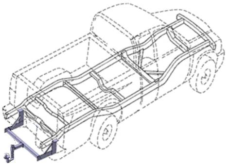
View of the towing device with low-mounted hook (ATDj)
|
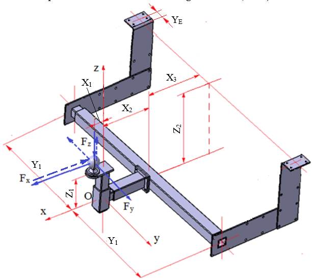
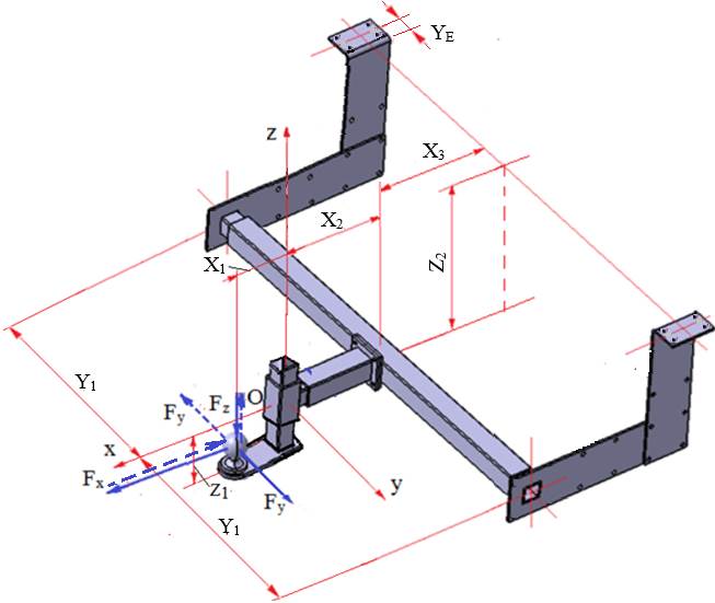
Diagram of the towing device with high-mounted hook (ATDs)
|
Diagram of the towing device with low-mounted hook (ATDj)
|
|
Notation: – Oxyz – the coordinate system (Ox – horizontal axis parallel to the longitudinal axis of the towing vehicle; Oy – horizontal axis parallel to the transverse axis of the towing vehicle; Oz – vertical axis parallel to the vertical axis of the towing vehicle); – X1 – positioning distance of the towing hook; – X2 – maximum positioning distance of the transverse column; – X3 – maximum horizontal positioning distance of the ATD-to-chassis joint (bolted joint); – Y1 – maximum half-width; – Z1 – maximum positioning height of the towing hook (for the ATDs variant the ball is above the origin of the coordinate system, for the ATDj variant it is below the origin); – Z2 – maximum vertical positioning height of the ATD-to-chassis joint (bolted joint); – YE – half-width of the chassis longitudinal member; – FX – axial force; FY – transverse force; FZ – vertical force. Notes. – the structure of the device is symmetrical with respect to the Oxz plane (the vertical plane of the towing vehicle); – given the real loads acting on the ATD in the vehicle's operating regimes (forward/reverse travel, left/right turns, acceleration/braking, uphill/downhill), the design must consider the loads at the towing hook in both directions (in the diagrams above the forces are drawn in two ways, with solid and dashed lines). | |
Product type
ATDs are detachable modular mechanical structures with no relative motion between their component elements.
Block diagram
Purpose and functions of the product
Purpose: coupling and towing trailers and caravans behind vehicles.
Main function: transmitting the loads (forces and moments) from the input I (the towing coupling) to the output E, materialised by two bolted joints to the chassis (body).
Auxiliary functions:
– possibility of adjusting the towing hook in the vertical plane for alignment with the towing vehicle;
– easy removal of the towing hook subassembly;
– compliance with the interchangeability requirements of the relevant standards;
– compliance with human and environmental protection requirements.
Main design parameters
According to UN/ECE Regulation No. 55 (Annex.1.1.1.1):
Trailer mass reduced to the towing hook (coupling), S = [30…200] kg.
Horizontal force at the towing hook (coupling), D = [0.5…5] kN.
Design data
External forces:
– FX = D [N], the horizontal axial force.
– FY = k FX [N], the horizontal transverse force; the following values are used: k = 0.2 for FX = [0.5…2) kN; k = 0.3 for FX = [2…3.5) kN; k = 0.4 for FX = (3.5…5] kN.
– FZ = S g [N]; take the gravitational acceleration g = 10 m/s2.
Dimensional constraints: X1, X2, X3, Y1, Z1, Z2; YE = 60 mm for FX ≤ 2500 N; YE = 70 mm for FX > 2500 N.
Operating and design constraints
Operating constraints: type of vehicle it is fitted to: passenger car or light commercial vehicle; type of external loading: constant, alternating, with shocks, etc.; temperature range (−30…40) °C.
Design and mounting constraints: hook mounting variant: ATDs or ATDj; protection against environmental factors: anti-corrosion; interchangeability: at the input, for the towing hook (coupling); modularity: the imposed dimensions can be modified (reduced).
Environmental constraints: use of eco-friendly materials and technologies, recycling of materials, protection of life, etc.