1. General aspects of preparing working drawings (Annex.9.0)
Definitions
A working (detail) drawing is a scaled graphical representation of an element that contains all the information (including text) needed to manufacture, mark and package the element (part).
A subassembly drawing is a scaled graphical representation of a subassembly that contains all the information (including text) needed to manufacture and mark its component elements, and to assemble and package it.
Structure of the working (subassembly) drawing
Main requirements to be shown in working (subassembly) drawings:
– the geometric, functional and constructive-technological shapes, using a minimum number of views and sections;
– all dimensions needed for manufacture and operation;
– the surface quality;
– the required heat treatment and mechanical properties;
– how the component elements are connected (joined, assembled) (subassembly drawings only);
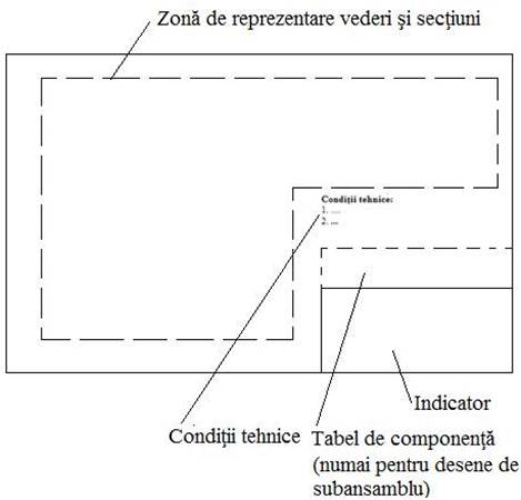
– the parts list (subassembly drawings only), containing information on the component parts.
Usual standard formats:
A4 (210 × 297); A3 (297 × 420); A2 (420 × 594); A1 (594 × 841); A0 (841 × 1189).
The title block contains the data identifying the drawing.
The Technical requirements field gives, as text, manufacturing aspects that cannot be shown graphically: general accuracy class, dimensions referring to several surfaces, heat treatment, outer protection, marking, packaging etc.
2. General recommendations for preparing working (subassembly) drawings
– working or subassembly drawings are usually made at full scale 1:1; for small dimensions, the whole drawing or only certain partial sections may be drawn at an enlarged scale (2:1, 5:1, 10:1, 20:1); for large dimensions, reduced scales (1:2, 1:5, 1:10, 1:20) may be used; for the project, a 1:1 scale is recommended;
– working or subassembly drawings contain one or more views and/or full, partial or in-view sections;
– dimensions are written so that they can be read from below and from the right of the projection (anticlockwise) relative to the edge of the sheet carrying the title block;
– hidden elements drawn with dashed lines should not be dimensioned;
– dimensions are given from a reference surface (dimensioning datum), so that the dimensions or dimension chains can be checked continuously both while drawing and during manufacture;
– technological dimensioning is recommended, i.e. dimensions given from reference datums chosen on technological grounds; for functional dimensions – which govern operation and/or assembly – chain dimensioning may be used, resulting in mixed dimensioning;
– roughness is indicated only once for a surface, in the projection in which that surface is dimensioned, with the tip of the symbol pointing to the surface; the texture of fillet surfaces is not marked (a fillet takes the roughness of the smoothest adjacent surface);
– when most surfaces have the same roughness, it is written above the title block;
– the heat treatment is given as text in/under the Technical requirements field when it concerns the whole part, and/or in the drawing field, specifying the depth of the treated layer and the mechanical properties of the material;
– for functional surfaces, in addition to the dimensions, the dimensional tolerances (deviations) and the form and position tolerances are written.
3. Specifics of producing working drawings with AutoCAD
Recommendation
To produce the drawings, AutoCAD can be downloaded from students.autodesk.com after creating a student account. The student version is free and marks the plotted (printed) drawings with the message "Student Version", which matches our purpose of using AutoCAD for training only.
Working stages
A. Preparing the AutoCAD environment and planning the drawing
– open a new file (application);
– from the menu Tools → Options, configure the screen, the file save locations, the printer data, the units (mm), preferences, coordinate systems etc.;
– select the MODEL space working environment;
– analyse the sketch of the working drawing and plan a logical layer structure, so that the drawing can be developed simply and clearly following the construction and assembly structure, and the working drawings can later be produced easily; for the drawing in Machine Elements project no. 1, it is recommended to create a layer for each element (part), in which its contour is drawn, plus auxiliary layers (axes, dimensions, hatching, positioning etc.);
– create the layers with the icon  or the command Format → Layer; use the same element names as in the calculations (names that are kept in the parts list as well); since the drawing will be used in the workshop printed on monochrome (black/white) paper, black/white is recommended for readability, separating the entities by line type and thickness;
– activate OSNAP mode by pressing F9 or clicking the button on the bottom bar ( ) and select the needed functions (intersection, endpoints, midpoint, tangents, parallels etc.);
– if only horizontal and vertical lines are used, activate ORTHO mode by pressing F8 or the button on the bottom bar.
B. Producing the working drawings
This stage follows the completion of the assembly drawing. Working drawings are produced for all non-standard elements.