Mogan Gh.L., Buzdugan I.D. Design of automotive towing devices. Transilvania University of Brașov.
Definitions
A working (detail) drawing is a scaled graphical representation of an element that contains all the information (including text) needed to manufacture, mark and package the element (part).
A subassembly drawing is a scaled graphical representation of a subassembly that contains all the information (including text) needed to manufacture and mark its component elements, and to assemble and package it.
Structure of the working (subassembly) drawing
Main requirements to be shown in working (subassembly) drawings:
– the geometric, functional and constructive-technological shapes, using a minimum number of views and sections;
– all dimensions needed for manufacture and operation;
– the surface quality;
– the required heat treatment and mechanical properties;
– how the component elements are connected (joined, assembled) (subassembly drawings only);
– the parts list (subassembly drawings only), containing information on the component parts.
Usual standard formats:
A4 (210 × 297); A3 (297 × 420); A2 (420 × 594); A1 (594 × 841); A0 (841 × 1189).
The title block contains the data identifying the drawing.
The Technical requirements field gives, as text, manufacturing aspects that cannot be shown graphically: general accuracy class, dimensions referring to several surfaces, heat treatment, outer protection, marking, packaging etc.
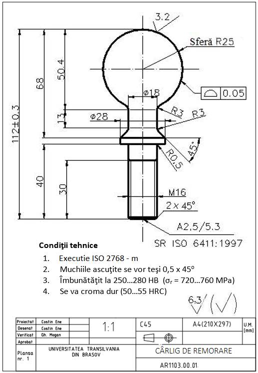
General recommendations for preparing working drawings
General aspects
Working drawings are made at a given scale, with classical drawing instruments or with specialised software (AutoCAD, CATIA etc.).
Working drawings are generally prepared in the following stages:
– choosing the scale according to the size and complexity of the part, per SR EN ISO 5455:1997; working or subassembly drawings are usually made at full scale 1:1; for small dimensions, the whole drawing or only certain partial sections may be drawn at an enlarged scale (2:1, 5:1, 10:1, 20:1); for large dimensions, reduced scales (1:2, 1:5, 1:10, 1:20) may be used; for the Machine Elements project, a 1:1 scale is recommended;
– choosing the drawing format according to the chosen scale, the number of projections, the overall dimensions of the part etc.; working or subassembly drawings contain one or more views and/or full, partial or in-view sections;
– producing the scaled drawing itself, in principle through the following phases: setting the line thicknesses, drawing the symmetry axes, the contour lines, the auxiliary lines, the dimension lines, arrows and hatching, writing the tolerances and roughness values, filling in the title block etc.;
– checking and signing the drawing.
Dimensioning in working drawings
Dimensioning is the operation of writing on the drawing of a part the dimensions of the simple geometric shapes that make up the part, and the dimensions that fix their relative positions.
Recommendations for dimensioning:
– Technological dimensioning: dimensions are given from reference datums chosen on technological grounds, so that the dimensions or dimension chains can be checked continuously during manufacture as well.
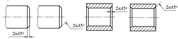
– Dimensioning chamfers
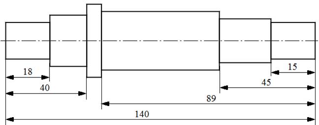
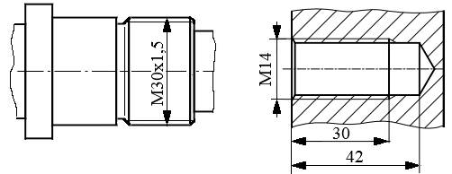
– Dimensioning threads
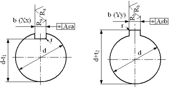
– Dimensioning keyways
Writing tolerances and deviations (SR ISO 406/1991)
For some functional surfaces, in addition to the dimensions, the following may be specified:
– Dimensional tolerances (deviations)
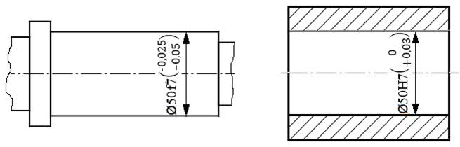
Components of a toleranced dimension: the nominal size (50), the symbol of the tolerance zone and grade (H7, f7) and, optionally (in brackets), the limit deviations; Annex.T.05 gives the limit deviations for various tolerance zones.
– Position tolerances (deviations)
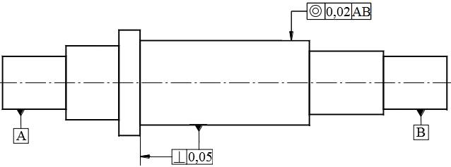
The position tolerance values (parallelism  ; perpendicularity
  ; angularity
  ; concentricity or coaxiality
  ; symmetry
  ) can be taken from Annex.T.06.
– Form tolerances (deviations)
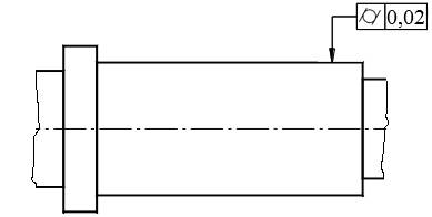
The form tolerance values (roundness  ; cylindricity
  ; straightness
  ; flatness
  ; profile of a surface
  ) can be taken from Annex.T.07.
– Tolerances for untoleranced dimensions (no function-related deviations): the general tolerances for linear dimensions (SR EN 22768, ISO 2768, STAS 2300) are grouped into 4 tolerance classes (fine, f; medium, m; coarse, c; very coarse, v); the deviations can be determined from Annex.T.04; they are indicated as text under Technical requirements (e.g. ISO 2768-m; Tolerances m STAS 2300).
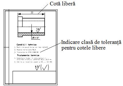
Indicating surface texture (roughness)
When part surfaces are produced by various processes (casting, forging, turning, broaching, milling, drilling, reaming, grinding, polishing, lapping, honing etc.), small asperities (micro-irregularities) result, often invisible to the naked eye.
Roughness is a measure of these micro-irregularities after a manufacturing process (the roughness terms are defined in SR ISO 4287:2000). The roughness of a surface is commonly assessed in two ways:
– Arithmetic mean deviation of the profile Ra: the arithmetic mean of the absolute values of the profile deviations within a sampling length.
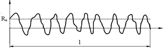
Possible values of the roughness Ra [μm]: 0.012; 0.025; 0.05; 0.1; 0.2; 0.4; 0.8; 1.6; 3.2; 6.3; 12.5; 25; 50; 100 (the values in bold are common in practice); Annex.T.03 gives the roughness Ra [μm] for various machining processes.
– Mean height of the irregularities Rz: the mean of the absolute values of the 5 highest peaks and the 5 deepest valleys within a sampling length.
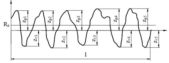
Possible values of the roughness Rz [μm]: 0.025; 0.05; 0.1; 0.2; 0.4; 0.8; 1.6; 3.2; 6.3; 12.5; 25; 50; 100; 200; 400; 800; 1600.
The symbols used to indicate surface roughness are given in SR EN ISO 1302/2002.

a – basic symbol; b – material removal required; c – material removal prohibited; d – indicates specific surface characteristics; e – all surfaces must have the same texture.
Meaning of the indications associated with the roughness symbols (common examples)

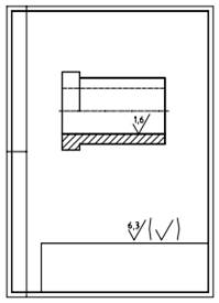
When most surfaces have the same roughness, the symbol with the general roughness value Ra is placed above the title block; the roughness symbol without a value, in brackets, indicates that other surfaces have different roughness values marked individually.
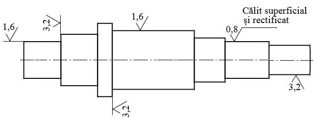
Roughness is indicated only once for a surface, usually in the projection in which that surface is dimensioned, with the tip of the symbol pointing to the surface concerned.
Indicating the material and heat treatments
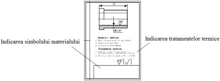
The material/steel symbol (Annex.M.01) is written in the dedicated box of the title block. Heat treatments are given as text in/under the Heat treatments field when they concern the whole part, and/or in the drawing field, specifying the depth of the treated layer and the mechanical properties of the material.