A. Loading diagram and design data
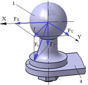
Loading diagram
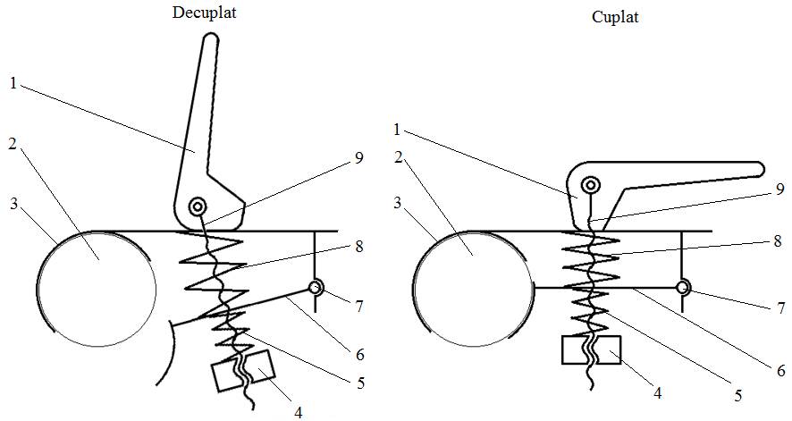
Functional diagrams
Design data
External forces: FX, FY, FZ; the resultant (radial) force is calculated:
Fr = 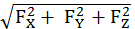 (Calc.8.5.1).
Operating constraints: temperature T = (−30…40) °C; outdoor working environment with high humidity.
Design constraints: interchangeability with the coupling systems in use in the EU.
Note. The straight towing hook with ball (Annex.3.1.1) is connected to the towing coupling (Annex.3.1.2) through a spherical kinematic pair fitted with a locking mechanism that ensures and maintains permanent contact on the spherical surface.
B. Choice of materials and heat treatments
The elements in contact, 3 and 2, are made of steel (e.g. C45, C60, E360; Annex.M.01).
The spherical pair is lubricated with general-purpose grease, whose main characteristics are the allowable pressure pa = 10…12 MPa and the dropping point Tmax = (75…85) °C.
C. Design of the constructive shapes
Constructive structure
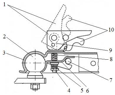
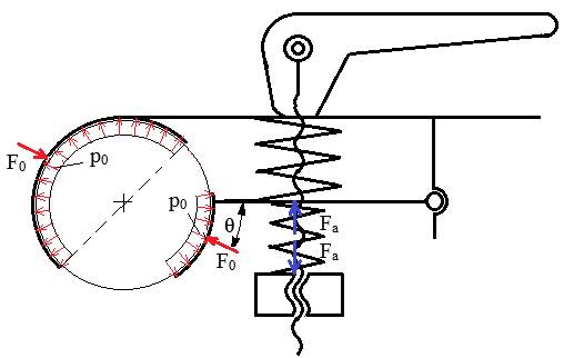
Key: 1 – coupling/uncoupling handle; 2 – towing hook; 3 – towing coupling body; 4 – nut; 5 – preload spring; 6 – clamp; 7 – pin joint; 8 – spring returning the clamp to the uncoupled position; 9 – eye bolt; 10 – self-locking latch.
D. Calculation models and checking
Calculation models (Annex.8.5.1)
Case I: spherical pair without external load (preloaded by the cylindrical helical compression spring)
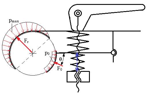
Case II: spherical pair under external load (the radial force)
Assumptions and loads for checking the ball joint:
– pressure distribution in the contact zone: cosine-shaped under external load (Case II);
– the spherical pair is considered loaded by the radial force only.
Calculation data
– loading: the radial force Fr;
– dimensions: the ball diameter Ds;
– materials: grease with allowable pressure pa.
Calculation relations
The maximum actual pressure from Annex.8.5.1, with r = Ds/2, becomes
pmax = 
 =
=  (Calc.8.5.2).
Contact pressure check
pmax ≤ pa.
If this relation is not satisfied, the ATD loads must be changed.