1. General aspects of preparing assembly drawings
Definitions
The assembly drawing is a graphic representation (to scale), on a sheet of standard size, of a set of elements and subassemblies in defined relative positions, taking into account the functional and constructive requirements resulting from the technical specifications and the design calculations.
The assembly drawing is a graphic representation (to scale) that shows the composition, operation, shapes and construction of the component elements and subassemblies, as well as the technological possibilities for their manufacture and assembly.
Structure and requirements of assembly drawings
General structure
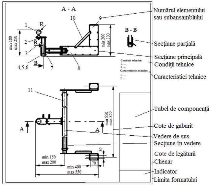
Main aspects to show in an assembly drawing
An assembly drawing must show:
– the shapes and positions of the component elements and subassemblies, using a minimum number of views and sections;
– how it works;
– how it is assembled (mounted);
– the assembly and functional dimensions;
– how it connects to the neighbouring assemblies and/or subassemblies.
Usual standard sheet sizes
A4 (210 × 297); A3 (297 × 420); A2 (420 × 594); A1 (594 × 841); A0 (841 × 1189).
The title block contains the data that identify the drawing; its shape and dimensions are given in Annex.ST.00.
The parts list contains information about the component parts and subassemblies; its shape and dimensions are given in Annex.ST.00.
Dimensioning the assembly drawing
Overall dimensions give the size of the assembly (width, length, height) in its extreme positions (minimum or maximum, closed or open, up or down);
Interface dimensions give the dimensions of the elements in the zone where they connect to the adjacent assemblies; for the towing device, show the radius of the tow ball and the sizes and positions of the mounting holes to the chassis;
Assembly dimensions give the dimensions (and sometimes roughness values) needed for assembly.
The Technical requirements field gives, as text, aspects of the assembly drawing that cannot be shown graphically (e.g. external protection, marking, packaging).
The Technical characteristics field gives numerical values that describe the product's performance (e.g. forces, lengths, speeds, powers, etc.).
2. General recommendations for representation in assembly drawings
The assembly drawing is usually made at full scale 1:1; for small dimensions, the whole drawing or only certain partial sections can be made at an enlarged scale (2:1, 5:1, 10:1, 20:1); for large dimensions, reduced scales can be used (1:2, 1:5, 1:10, 1:20); for Machine Elements project no. 1 the recommended scale is 1:1.
The assembly drawing contains a main view and one or more views and/or full, partial or local sections; for Machine Elements project no. 1, the top view can be chosen as the main view, placed in the lower left part of the sheet (A1 or A0), with a main section through the vertical longitudinal plane of symmetry, plus partial and local sections.
If elements and subassemblies can take variable relative positions, the assembly drawing shows one of the extreme positions; for the towing device (Machine Elements project no. 1), draw the positions that give the maximum dimensions.
Each distinct element or subassembly is identified by an item number that matches its row in the parts list; the item number of an element or subassembly is marked only once, in the view or section where it is most clearly identifiable; item numbers are usually marked successively, in increasing order, clockwise; the item numbers differ from those used in the calculation algorithm (the assembly drawing also includes fasteners, auxiliary parts, etc.), but the names are kept.
3. Specifics of producing the assembly drawing with AutoCAD
Recommendation
For the graphic documentation, the AutoCAD package can be downloaded from students.autodesk.com/ after creating a student account. The student version is free and is identified by the "Student Version" mark on plotted (printed) drawings, which matches our purpose of using AutoCAD for training only.
Work stages
A. Preparing the AutoCAD environment and planning the drawing
– open a new file (application);
– from the menu Tools → Options, configure the screen, file save locations, printer data, units of measurement (mm), preferences, coordinate systems, etc.;
– select the MODEL space working environment;
– analyse the sketch of the assembly drawing and design a logical layer structure, so that, on the one hand, the drawing can be developed simply and clearly following the constructive and assembly structure, and on the other hand, the working drawings can later be prepared easily; for the project drawing it is recommended to create one layer per element (part), in which its outline is drawn, plus auxiliary layers (axes, dimensions, hatching, positioning, etc.);
– create the layers using the icon  or the commands Format → Layer; use the same element names as in the calculations (names that are also kept in the parts list); since the drawing will be used in the workshop as a monochrome (black/white) paper print, use black/white for better legibility and distinguish entities by line type and thickness;
– turn on OSNAP by pressing F9 or clicking the button in the bottom bar ( ) and select the snap modes needed (intersection, endpoints, midpoint, tangent, parallel, etc.);
– if only horizontal and vertical lines are used, turn on ORTHO mode by pressing F8 or the button in the bottom bar.
B. Drawing the elements in the assembly drawing as the calculations progress through the design algorithm
For the assembly drawing of the Automotive Towing Device, it is suggested to start with section A-A, where the elements are drawn legibly in the order of the calculation stages. This sequence is shown in separate documents Ex.ACAD.3.8, Ex.ACAD.4.9 … Ex.ACAD.8.7, accessible from the Main design algorithm for Automotive Towing Devices (ATD).