1. Analysis model and input data
Analysis model
Analysis model in the XYZ coordinate system of the ATD
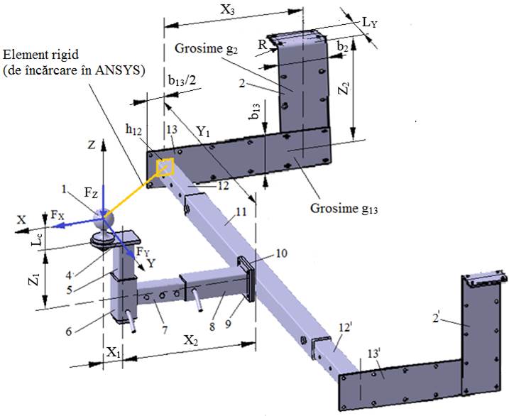
Analysis model in the ANSYS coordinate system
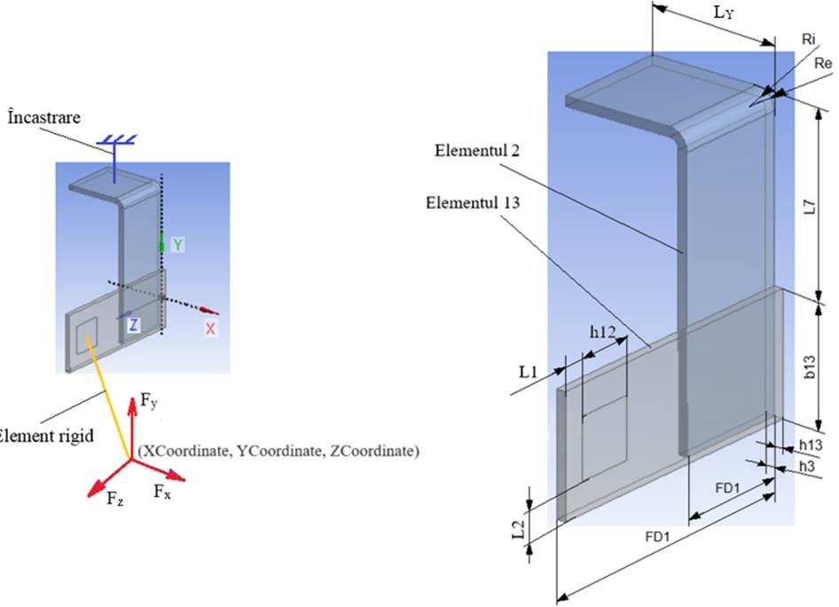
Input data
Forces: FX = 1500 N, FY = 300 N, FZ = 700 N.
Geometric parameters: X1 = 80 mm, X2 = 220 mm, X3 = 150 mm, Y1 = 550 mm, Z1 = 180 mm, Z2 = 250 mm; LY = 120 mm; Lc = 70 mm; b2 = 120 mm; b13 = 120 mm; g2 = 10 mm; g13 = 15 mm; h12 = 50 mm; R = 20 mm.
Material: S235, weldable general-purpose steel, for element 13; E335, steel for mechanical construction, for element 2.
Operating constraints: temperature T = (−30…40) °C.
Parameters of the ANSYS model
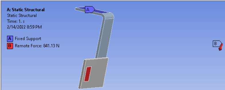
Forces: Fx = FY/2 = 150 N, Fy = −FZ/2 = −350 N, Fz = FX/2 = 750 N.
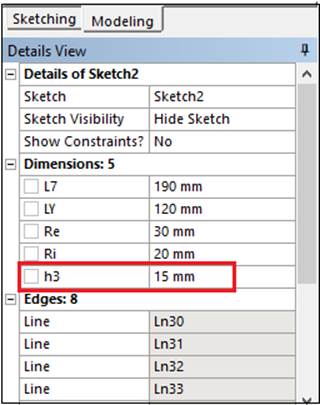
Geometric parameters: h13 = g13 = 15 mm, h3 = g2 = 10 mm, b13 = b13 = 120 mm, L7 = 190 mm, LY = 120 mm, Ri = R = 20 mm, Re = R + g2 = 30 mm, h12 = h12 = 50 mm; L1 = 35 mm, L2 = 35 mm; FD1 = 120 mm for Element 2 and FD1 = 270 mm for Element 13; coordinates of the force application point: XCoordinate = Y1 + g13 = 565 mm; YCoordinate = Z1 + Lc = 250 mm; ZCoordinate = X1 + X2 + X3 + b2/2 = 510 mm.
Material: for S235 steel, σat = σ02/c = 235/1.3 = 180 MPa (since the FEA model is more accurate, a lower safety factor c = 1.3 was adopted than for the classical, less accurate design models, where usually c > 2); for E335 steel, σat = σ02/c = 335/1.3 ≈ 250 MPa; allowable contact stresses: σas = 90 MPa, the allowable steel-on-steel normal crushing stress, and τas = 45 MPa, the allowable steel-on-steel tangential contact stress.
Viewing the support (fixed) zone and the applied forces and moments
🖱
🖱
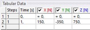
2. Results
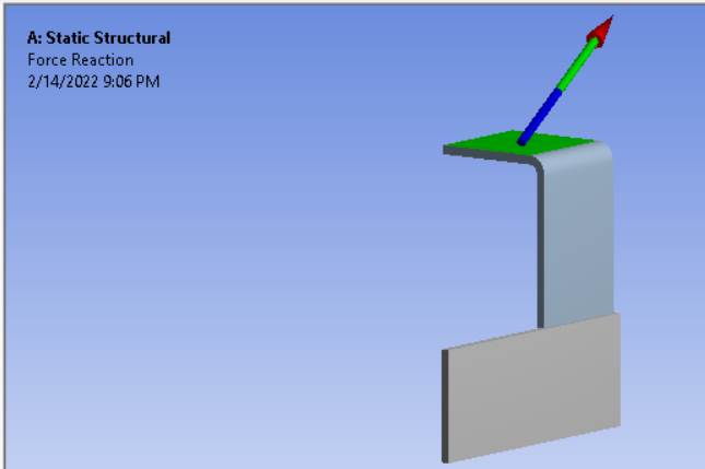
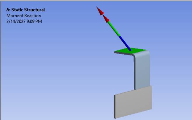
Viewing the forces in the reaction zone
🖱

🖱

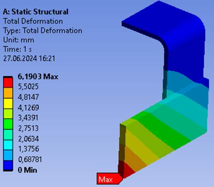
Viewing the displacements
🖱 → the model appears
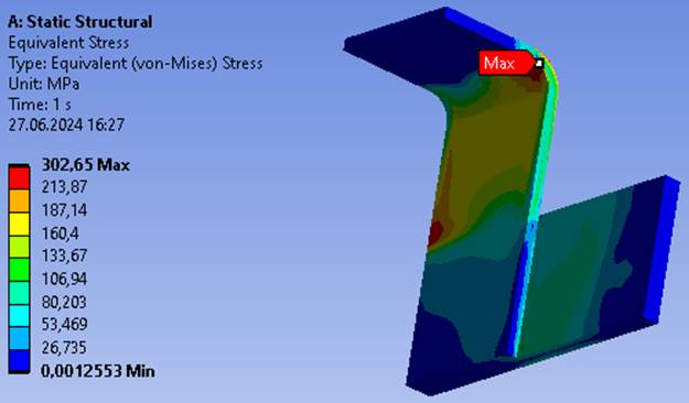
Viewing the stresses
Equivalent stresses on the global model
🖱  → the model appears
Equivalent stresses on the model of Element 13
🖱 
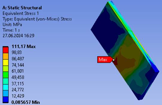
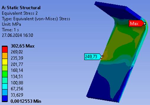
Equivalent stresses on the model of Element 2
🖱 
Viewing the pressures and stresses in the contact zones
Pressures on the contact surfaces
🖱
🖱
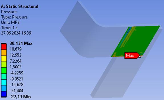
Friction stresses on the contact surfaces
🖱
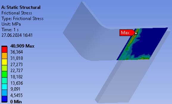
3. Checks
Stiffness (deflection) check
δ ≤ δa; 6.19 ≤ 10 mm (satisfied).
Note. The allowable deflection is set by the operating conditions.
Check under combined loading
σech_max ≤ σat; 302.65 ≤ 196 MPa (NOT satisfied),
where σech_max is the maximum equivalent stress in the figure above.
If the inequality above is NOT satisfied, one of the following options can be chosen:
a. choose a better material;
b. change the geometry by increasing one or more dimensions;
c. choose another material and change the geometry.
In this application, option b is adopted and the analysis steps are repeated, as detailed below.
Changing the geometric parameters
Activating the DesignModeler module
🖱🖱 → the window
  opens with the geometric model.
Changing the section dimensions
🖱 → 🖱
→ 🖱 →
→  : [change the dimension h3].
Saving the model
🖱 → 🖱
→ 🖱 .
.
Updating the geometric model in the FEA model
🖱 →
→ 
 → 🖱
→ 🖱 
Solving the modified model
 → 🖱
→ 🖱 .
.
Post-processing the modified model
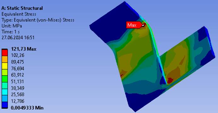
Equivalent stresses on the global model
🖱 → the model appears.
Re-check under combined loading
σech_max ≤ σat; 121.73 ≤ 180 MPa (satisfied), where σech_max is the maximum equivalent stress in the figure above.
Check of the normal contact pressure
pmax ≤ σas; 30.131 ≤ 90 MPa (satisfied),
where pmax is the maximum pressure in the figure above.
Check of the tangential (friction) contact stress
τmax ≤ τas; 40.909 ≤ 45 MPa (satisfied),
where τmax is the maximum tangential contact stress (frictional stress) in the figure above and τas the allowable tangential contact stress.