1. Analysis model and input data
Analysis model
Loading diagram in the XYZ coordinate system of the ATD
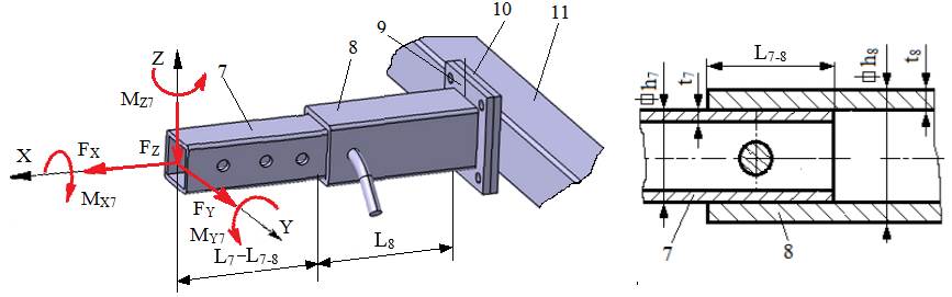
Analysis model (FEA) in ANSYS
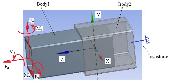
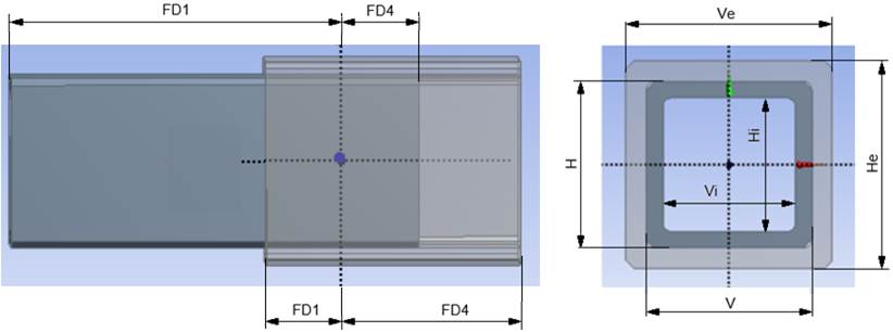
Geometric parameters in ANSYS
Input data
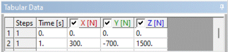
Forces: FX = 1500 N, FY = 300 N, FZ = 700 N.
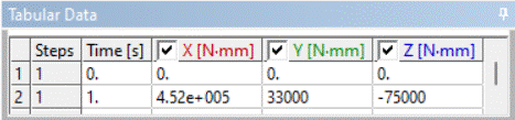
Moments: MX7 = 75000 Nmm, MY7 = 452000 Nmm, MZ7 = 33000 Nmm.
Geometric parameters: L7 = 115 (105) mm, L8 = 85 (95) mm; L7-8 = 60 mm; h7 = 50 mm, t7 = 5 mm, h8 = 60 mm, t8 = 5 mm.
Material: S235, weldable general-purpose steel.
Operating constraints: temperature T = (−30…40) °C.
Parameters of the ANSYS model
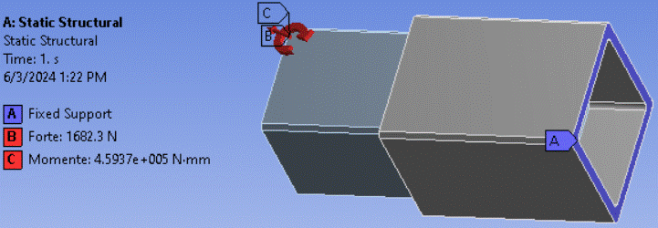
Forces: Fx = FY = 300 N, Fy = −FZ = −700 N, Fz = FX = 1500 N.
Moments: Mx = MY7 = 452000 Nmm, My = MZ7 = 33000 Nmm; Mz = −MX7 = −75000 Nmm.
Geometric parameters: He = 60 mm, Ve = 60 mm, H = 50 mm, V = 50 mm, Hi = 40 mm, Vi = 40 mm; FD1 = 30 mm and FD4 = 55 mm for Body2; FD1 = 85 mm and FD4 = 30 mm for Body1.
Material: S235, weldable general-purpose steel, with σat = σ02/c = 235/1.3 = 180 MPa (since the FEA model is more accurate, a lower safety factor c = 1.3 was adopted than for the classical, less accurate design models); allowable contact stresses: σas = 90 MPa, the allowable steel-on-steel normal crushing stress, and τas = 45 MPa, the allowable steel-on-steel tangential contact stress.
Viewing the support (fixed) zone and the applied forces and moments
🖱
🖱
🖱
2. Results
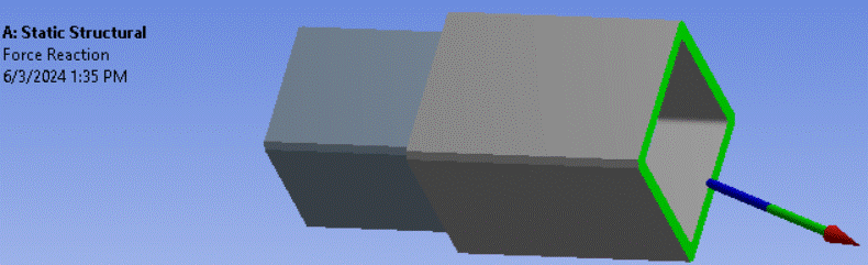
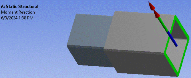
Viewing the forces in the reaction zone
🖱

🖱

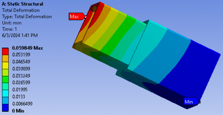
Viewing the displacements
🖱 → the model appears.
Viewing the stresses
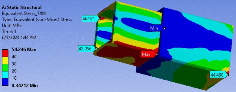
Equivalent stresses on the global model
🖱  → 🖱
→ 🖱 (marks local stress values at points) → [move the cursor and 🖱 click the point on the model where the stress value should be shown]; to delete a local value: 🖱
 (Label) → [🖱 select the value, then press the Delete key];
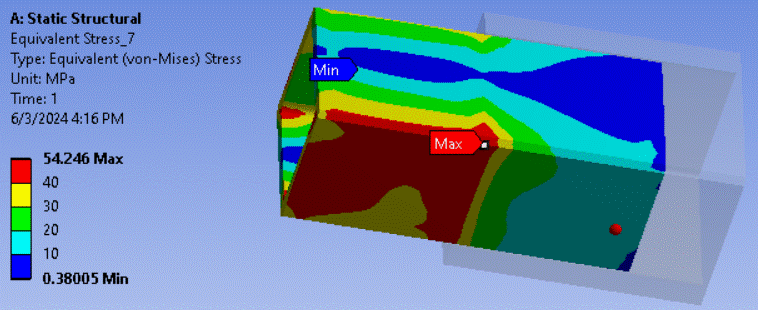
Equivalent stresses on the model of tube 7
🖱
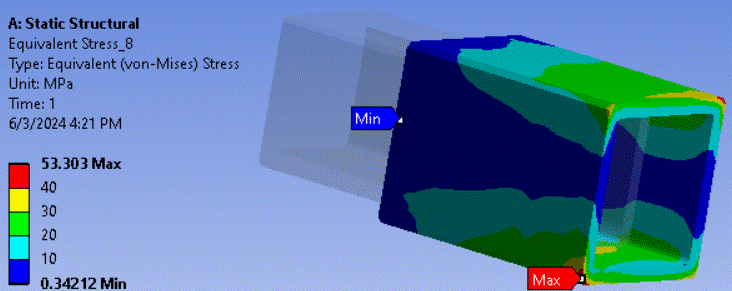
Equivalent stresses on the model of tube 8
🖱
Viewing the pressures and stresses in the contact zones
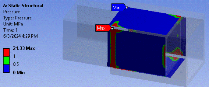
Pressures on the contact surfaces
🖱 → 🖱
→ 🖱
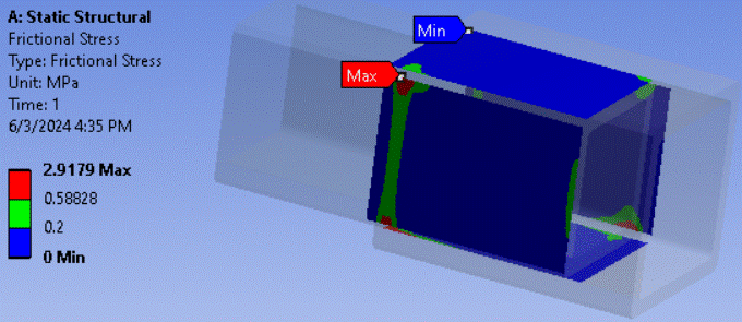
Tangential (friction) stresses on the contact surfaces
 → 🖱
→ 🖱
3. Checks
Deformation check
δ ≤ δa; 0.06 ≤ 5 mm (satisfied).
Note. The allowable deflection is set by the operating conditions.
Equivalent stress check
σech_max ≤ σat; 54.246 ≤ 132 MPa (satisfied),
where σech_max is the maximum equivalent stress in the figure above.
Normal contact pressure check
pmax ≤ σas; 21.33 ≤ 70 MPa (satisfied),
where pmax is the maximum pressure in the figure above.
Tangential contact stress check
τmax ≤ τas; 2.92 ≤ 40 MPa (satisfied),
where τmax is the maximum tangential contact stress (frictional stress) in the figure above and τas the allowable tangential contact stress.