1. Input data and results
Geometry data
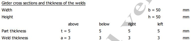
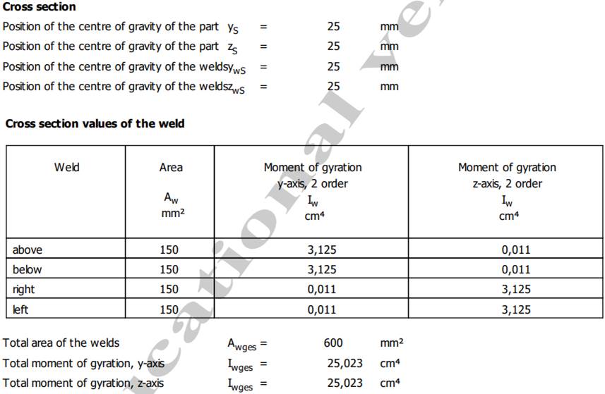
Meaning
– yS, zS – position of the centre of gravity of the part (beam section); ywS, zwS – position of the centre of gravity of the welds;
– Aw – area; Iw – second moment of area about the y/z axis; weld; above; below; right; left;
– Awges – total area of the welds; Iwges – total second moment of area about the y/z axis.
Loading data
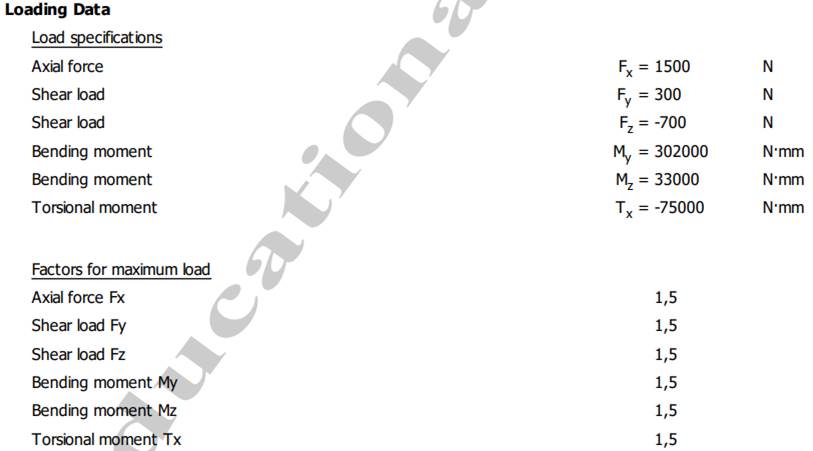
Meaning
– Load specifications – the loads in the section; Fx – axial force; Fy/Fz – shear loads; My/Mz – bending moments; Tx – torsional moment;
– Factors for max. load – the maximum-load factors.
Stresses in the welds
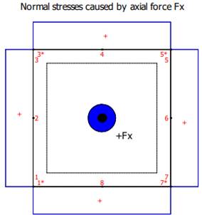
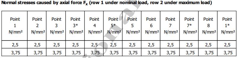
Normal stresses due to the axial force Fx (row 1 for the nominal force, row 2 for the maximum force)
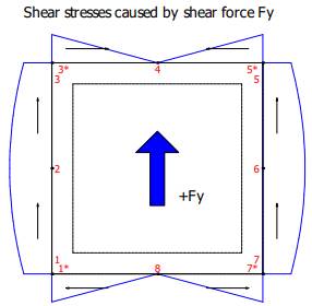
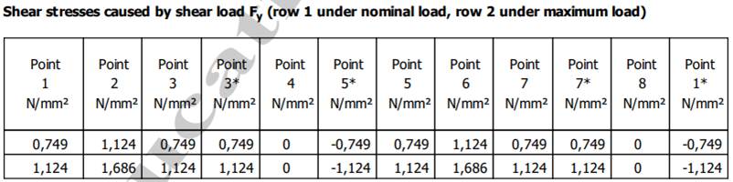
Stresses due to the shear force Fy (row 1 for the nominal force, row 2 for the maximum force)
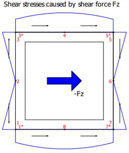
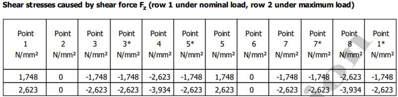
Stresses due to the shear force Fz (row 1 for the nominal force, row 2 for the maximum force)
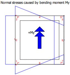
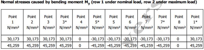
Normal stresses due to the bending moment My (row 1 for the nominal moment, row 2 for the maximum moment)
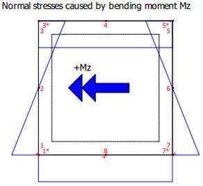
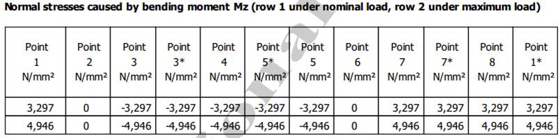
Normal stresses due to the bending moment Mz (row 1 for the nominal moment, row 2 for the maximum moment)
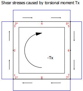
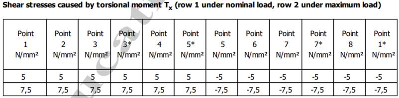
Shear stresses due to the torsional moment Tx (row 1 for the nominal moment, row 2 for the maximum moment)
Resultant stresses
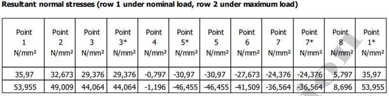
Resultant normal stresses (row 1 for the nominal loads, row 2 for the maximum loads)
Resultant shear stresses (row 1 for the nominal loads, row 2 for the maximum loads)
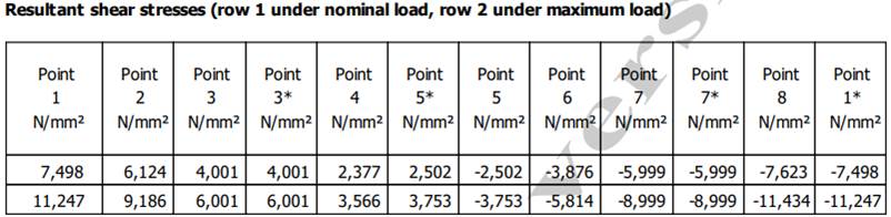
Maximum stresses in the weld
Stresses for each type of load
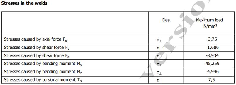
Maximum and allowable stresses

Meaning
– Normal stresses caused by the axial force Fx; shear stresses caused by the shear force Fy; shear stresses caused by the shear force Fz; normal stresses caused by the bending moment My; normal stresses caused by the bending moment Mz; shear stresses caused by the torsional moment Tx;
– Resultant normal stresses (maximum); resultant shear stresses (maximum);
– σres – maximum resultant normal stress; τres – maximum resultant shear stress; σzul – allowable normal stress; τzul – allowable shear stress.
2. Checks
Strength check for normal stresses
σres ≤ σzul; 53.955 ≤ 106.364 (satisfied).
Strength check for shear stresses
τres ≤ τzul; 11.247 ≤ 106.364 (satisfied).