Launching the beam-checking module
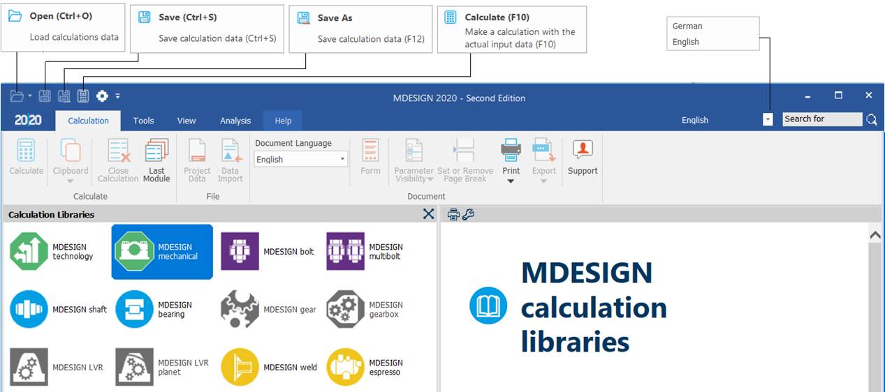
Main window of the MDESIGN package (Calculation Libraries)
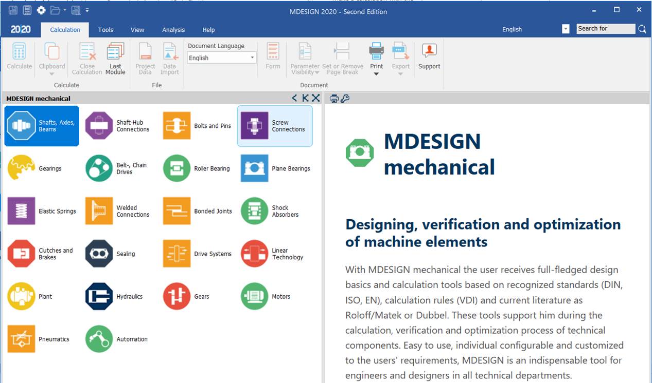
Main window of the MDESIGN mechanical group
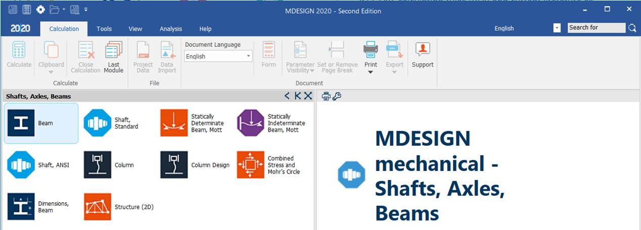
Main window of the MDESIGN Shafts, Axles, Beams group
Main window of the Beam module
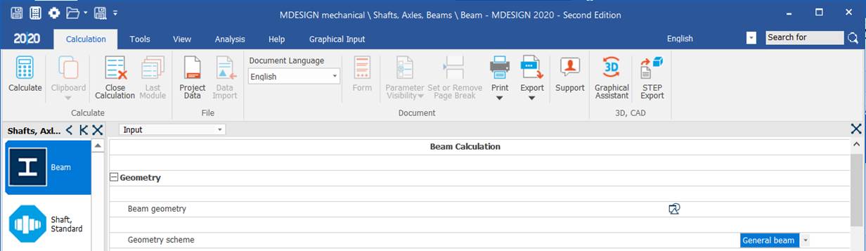
Input data page (Input)
General aspects
Selecting the Input page

Options

Meaning
– Single beam: used for constant-section cantilever beams with concentrated loads at the free end.
– General beam: used for all cases not covered by the previous one.
Position for the detailed calculation
Meaning
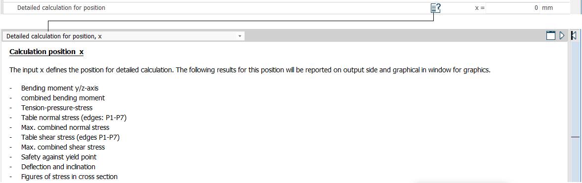
– Detailed calculation for position: x [mm].
– Calculation position: the input x defines the position for the detailed calculation. The following results for this position are shown in the results part and in the graphic windows: bending moments about the y and z axes; combined bending moments; tension-compression stresses; table of normal stresses (edges P1–P7); maximum combined normal stresses; table of shear stresses (edges P1–P7); maximum combined shear stresses; safety factor against yielding at a point; deflections and rotations; figures with the stresses in the cross-section.
Own weight

Meaning
Consideration of own weight: the beam's own weight can optionally be included in the static calculations (moments, stresses, deflections etc.).
Beam geometry
Meaning
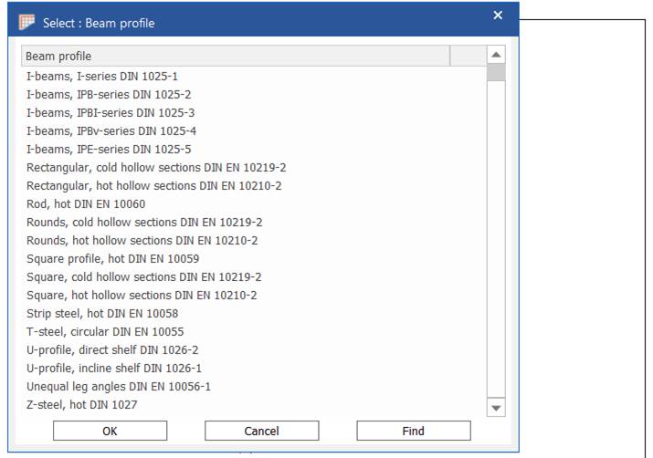
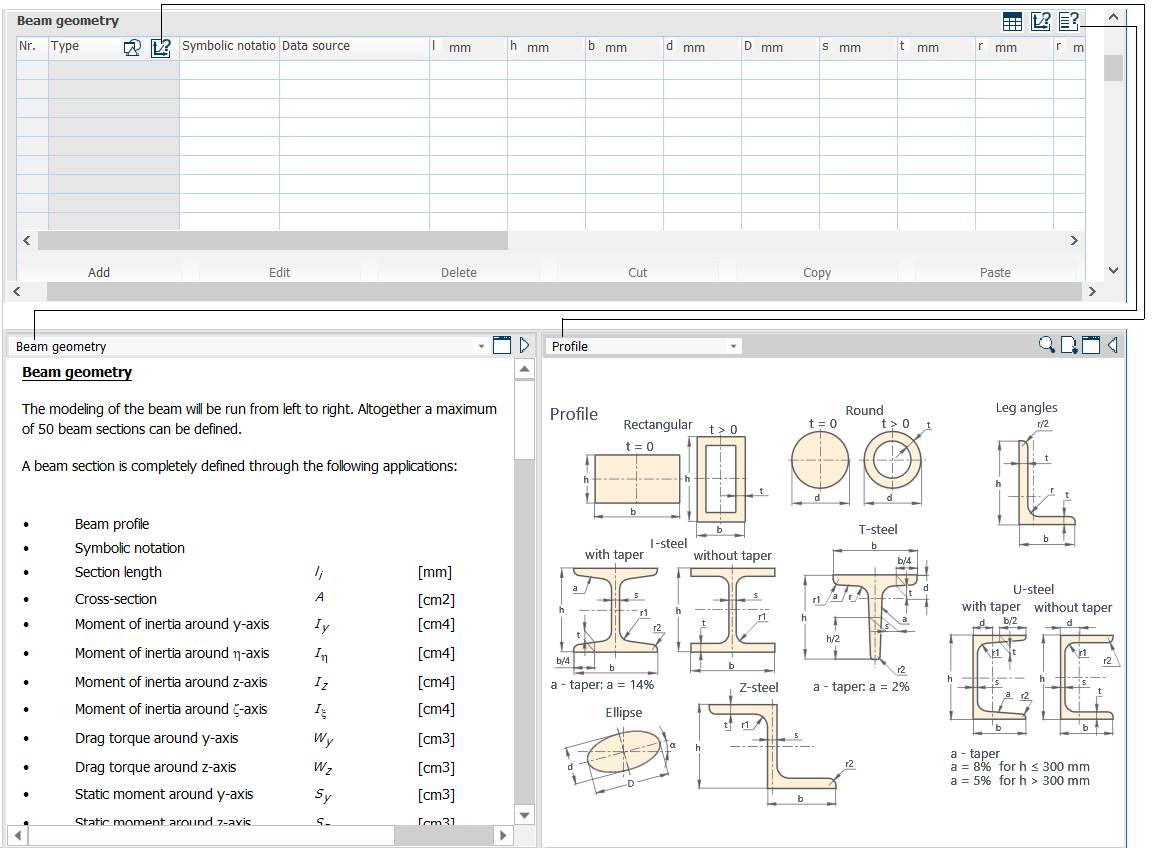
Beam geometry: the beam is modelled from left to right, with at most 50 sections. A beam section is fully defined by: beam profile; symbolic notation; section length li [mm]; cross-section A [cm2]; moments of inertia about the y, η, z and ξ axes, Iy, Iη, Iz, Iξ [cm4]; section moduli ("drag torque") about the y and z axes, Wy, Wz [cm3]; static moments about the y and z axes, Sy, Sz; data source, e.g. MDESIGN Database. Profile-specific data: strip steel – height h, width b [mm]; equal leg angles – height h, thickness t, radius r [mm], slope of ξ–ξ α [°], axis distances cy, cz [mm]; I-beams – height h, width b, middle width of the web plate s, middle width of the flange t, radius r [mm]; square and rectangular hollow sections – height h, width b, wall thickness t [mm]; round hollow sections – outer diameter, wall thickness t [mm]; rod – diameter D [mm]; T-steel – height h, width b, distance to the z–z axis d, web width s, radius r [mm]; unequal leg angles – height h, width b, leg thickness t, radius r [mm], slope of ξ–ξ α [°], axis distances cy, cz [mm]; U-profile – height h, width b, distance to the z–z axis d, web width s, flange width t, radius r [mm]; square profile – side b [mm]; Z-steel – height h, width b, web width s, flange width t, radius r [mm], slope of ξ–ξ α [°].
Bearings (supports)
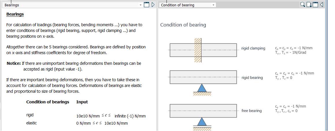
Meaning
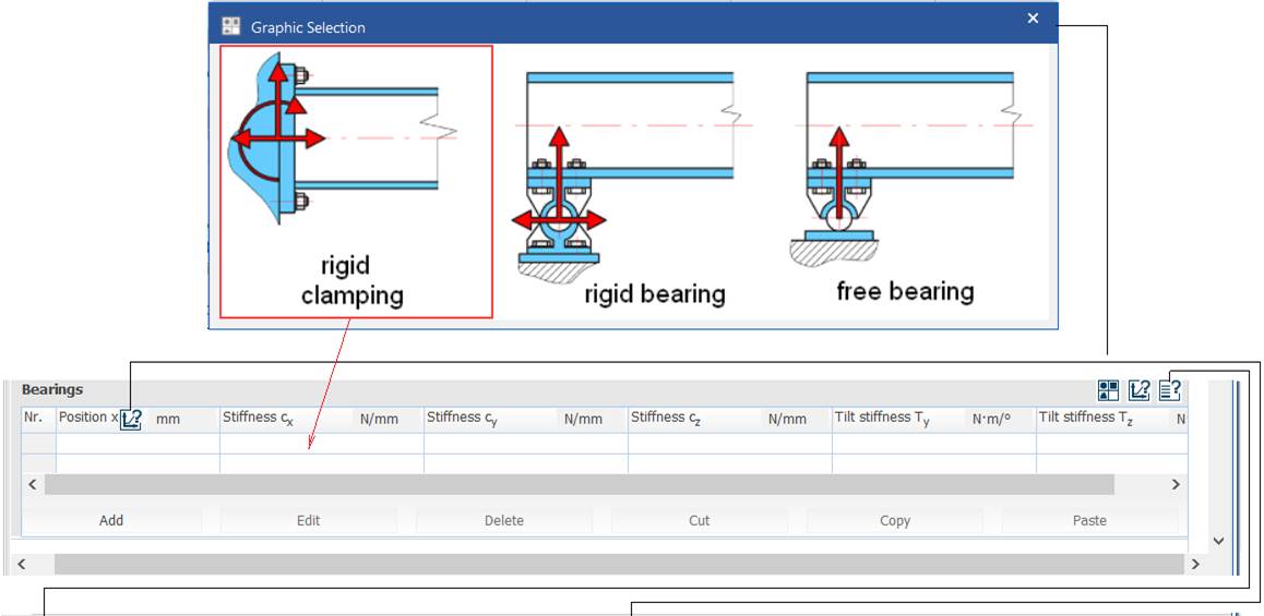
– Graphic selection: rigid clamping (fixed support), rigid bearing (pinned support), free bearing (simple support).
– Bearings: to calculate the support reactions (forces and moments), the bearing type (clamping, pinned, simple) and its position on the x axis must be entered. Up to 5 bearings can be defined, each by its position on the x axis and a stiffness for each degree of freedom.
Note: if the elastic deformations of a bearing are not important, the bearing is considered rigid (stiffness value −1). If they are important, they can be included in the reaction calculation; bearing deformations are elastic and proportional to the reaction forces.
Condition of bearings – Input:
rigid: 10e10 N/mm ≤ c ≤ infinite (−1)
elastic: 0 N/mm ≤ c ≤ 10e10 N/mm
– Stiffness cx, cy, cz [N/mm] (linear stiffnesses); tilt stiffness Ty, Tz [N/deg] (rotational stiffnesses).
Axial forces Fax
Options, parameters and comments
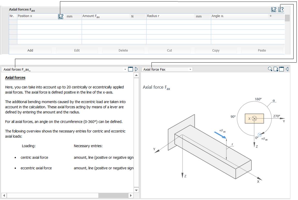
Meaning
– Axial forces Fax: position x [mm]; amount Fax [N]; radius r [mm]; angle α [°].
– Axial forces: up to 20 centric or eccentric axial forces can be included. An axial force is positive in the positive x direction. The additional bending moment caused by eccentric axial loading is taken into account. Axial forces acting through a lever arm are defined by their amount and their distance from the x axis (radius), plus a circumferential position angle (0–360°). Necessary entries:
– centric axial force: amount, line of action (positive or negative), position;
– eccentric axial force: amount, line of action (positive or negative), position, radius (lever arm).
Radial forces Fr
Options, parameters and comments
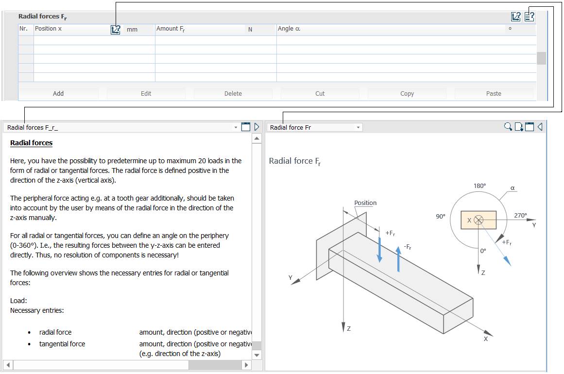
Meaning
– Radial forces Fr: position x [mm]; amount Fr [N]; angle α [°].
– Radial forces: up to 20 radial or tangential forces can be included. A radial force is positive in the positive z direction (vertical axis). A peripheral force, e.g. on a gear tooth, can be modelled as a radial force along z. For all radial or tangential forces a circumferential position angle (0–360°) is defined, so forces in the y–z plane can be entered directly. Necessary entries:
– radial force: amount, direction (positive or negative), position;
– tangential force: amount, direction (positive or negative), position, angle (e.g. direction relative to the z axis).
Bending moments Mb
Options, parameters and comments
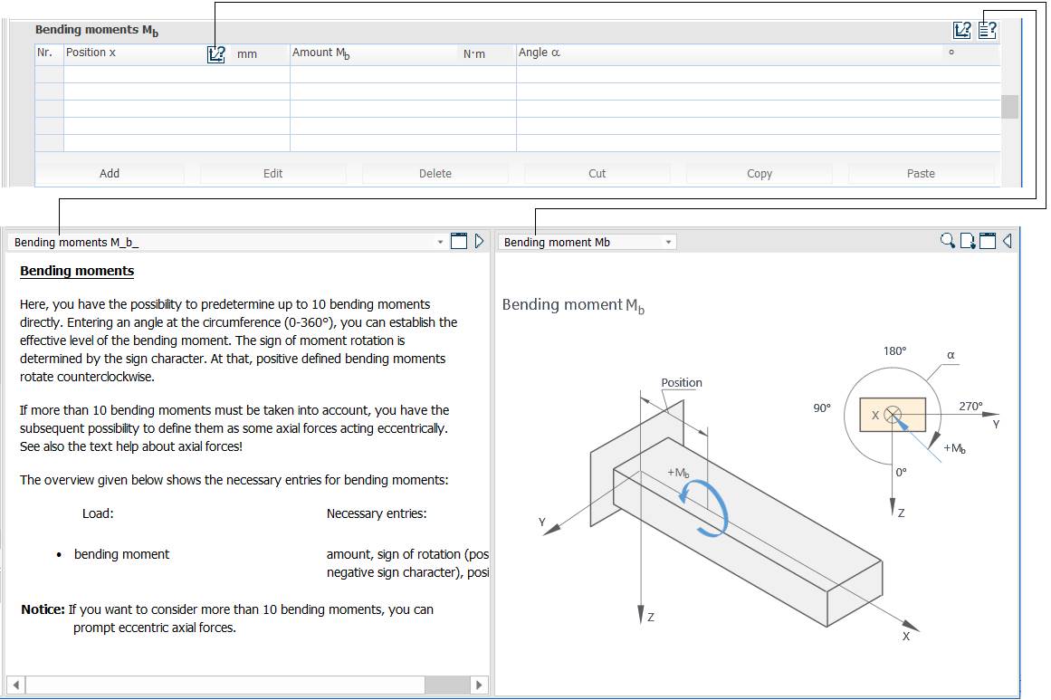
Meaning
– Bending moments Mb: position x [mm]; amount Mb [Nm]; angle α [°].
– Bending moments: up to 10 bending moments can be included. The circumferential position angle (0–360°) sets the effective direction of the moment; its sign is given by the sign of rotation, a positive moment being anticlockwise. If more than 10 bending moments occur, they can be defined as eccentric axial forces (see the help on axial forces). Necessary entries: amount, sign of rotation (positive or negative), position.
Distributed loads
Options, parameters and comments
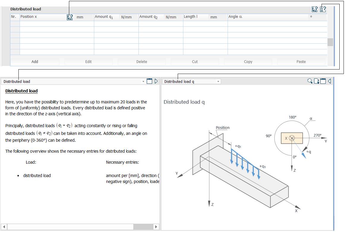
Meaning
– Distributed load: position x [mm]; amounts q1, q2 [N/mm]; length l [mm]; angle α [°].
– Distributed load: up to 20 uniform or variable distributed loads can be included. Each is positive in the z direction (vertical axis); it may be constant (q1 = q2) or variable (q1 ≠ q2), and a circumferential position angle (0–360°) can be set. Necessary entries: amount per mm, direction (positive or negative), position, loading length.
Torsion moments T
Options, parameters and comments
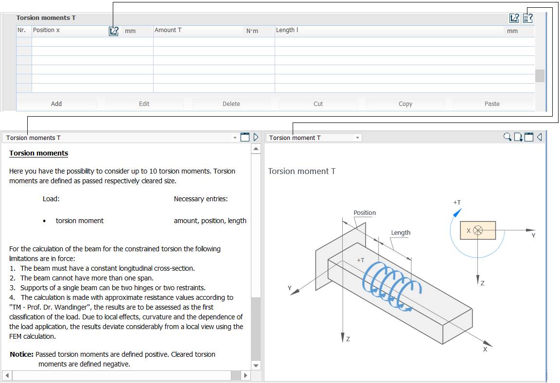
Meaning
– Torsion moments T: position x [mm]; amount T [Nm]; length l [mm].
– Torsion moments: up to 10 torsion moments can be included, defined as through-moments or end (head) moments. Necessary entries: amount, position, length.
The torsion calculation assumes that:
– the beam has a constant cross-section along its length;
– the beam has only one section;
– a single beam can have two pinned supports or two restraints;
– the calculation uses an approximate strength value according to "TM – Prof. Dr. Wandinger", the results being a first classification of the load. Because of local effects, curvature and the way the load is applied, the results can differ considerably from local values determined by FEM.
Note: through torsion moments are positive; end (head) torsion moments are negative.
Material data
Options, parameters and comments
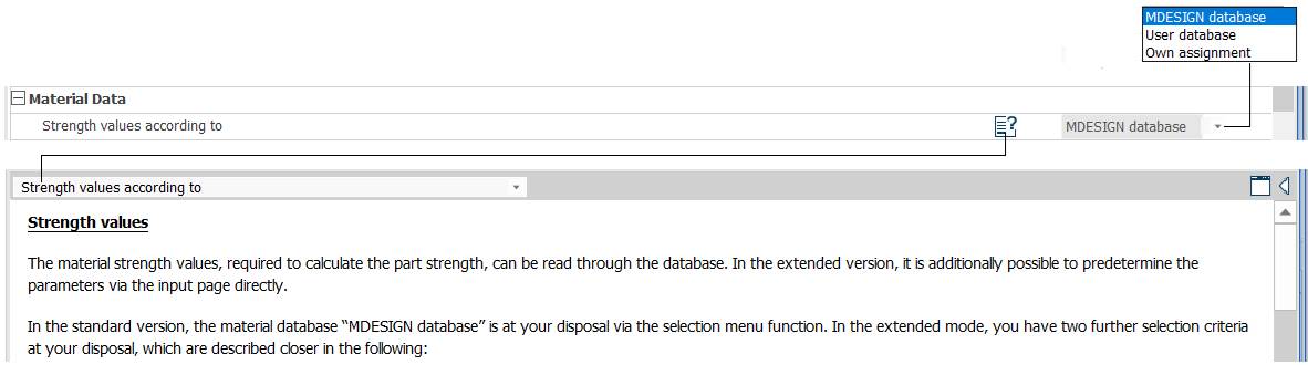

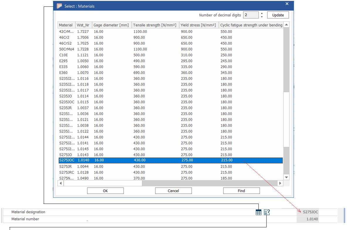
Meaning
– Strength values according to: MDESIGN database; user database; own assignment (manual entry).
– Strength values: needed for the strength calculation; they are associated with the material type chosen from the database.
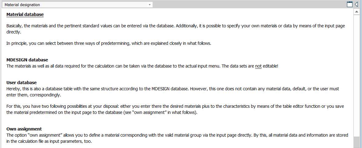
– Material database: the easiest way is to take materials and standard values from the database; own materials or data can also be entered directly on the input page, in one of three ways:
MDESIGN Database: the materials and data needed for the calculation are taken from the database through the input menu; the selected data cannot be edited.
User Database: a database table with the same structure as the MDESIGN database, initially empty; the user either enters any material and its properties in an editable table, or saves a material defined on the input page into it (see "Own assignment" below).
Own assignment: the properties of a material are defined as a separate group on the input page, so all material information is stored in the calculation file as input parameters. The material group can also be transferred with the save function into the "User database" table of the "Material data" module, making it available at any time for all calculations and users (e.g. network installations).
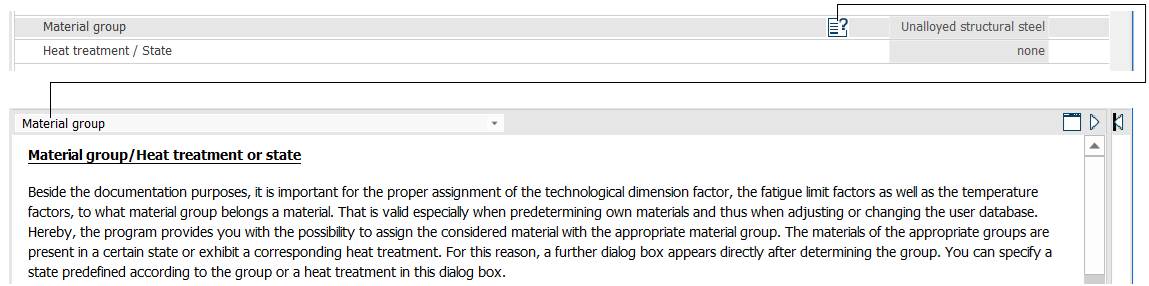
– Material group / heat treatment or state: besides documentation, this assigns the technological size factor, the fatigue limit factor, the temperature factor and the material group.
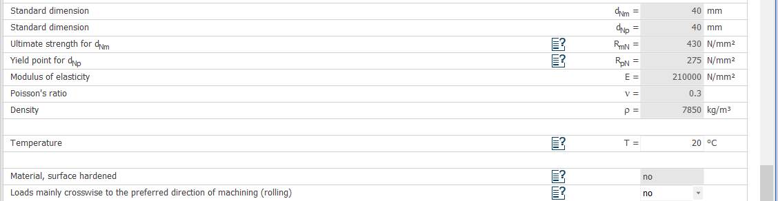
– Standard dimension (standard blank size); ultimate strength; yield point; modulus of elasticity; Poisson's ratio; density.