Machine Elements · Course project
Design of Automotive Towing Devices
A step-by-step design algorithm for a class F towing device: from the design brief and the static model, through the sizing of every element and joint, to numerical checks in MDESIGN and ANSYS and the full set of AutoCAD drawings.
| Authors | Gh.L. Mogan, I.D. Buzdugan | ||
|---|---|---|---|
| Institution | Transilvania University of Brașov | ||
| Product | Automotive Towing Device (ATD), UNECE R55 class F | Tools | MDESIGN · ANSYS · AutoCAD |
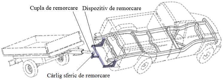
The device, subassembly by subassembly
The design follows the load path from the tow ball to the vehicle body. Each subassembly gets its own chapter.
- S1Towing hook and upper tie rodElements 1, 4, 5 · threaded joint 1-4, welded joint 4-5
- S2Upper column, body and lower tie rodElements 5–8 · tube-in-tube or pin joint 5-6, welded joint 6-7
- S3Lower tie rod to cross beamJoints 7-8 and 8-9
- S4Cross beamElements 9–12′ · bolted, welded, tube-in-tube and pin joints
- S5Side tie rodsElements 13, 13′ · welded joints 12-13
Design algorithm
General aspects and design brief
The towing device as a product, the objectives of the project and the data that define your variant.
Design of element 1 (towing hook) and subassembly S1
Towing hook, upper tie rod, upper column and the threaded and welded joints between them.
- 3.1Design of element 1 (towing hook)Sec.3.1Ex.3.1
- 3.2Design of element 4 (upper tie rod)Sec.3.2Ex.3.2
- 3.3Design of joint 1-4 (threaded joint)Sec.3.3Ex.3.3
- 3.4Design of element 5 (upper column)Sec.3.4Ex.3.4
- 3.5Design of joint 4-5 (welded joint)Sec.3.5Ex.3.5
- 3.6Checking element 4 (upper tie rod) with MDESIGNGuide.3.6Ex.3.6
- 3.7Checking joint 4-5 (welded joint) with MDESIGNGuide.3.7Ex.3.7
- 3.8Representation in the assembly drawing, stage 3Guide.ACAD.01Ex.ACAD.3.8
Design of subassembly S2
The connection between the upper column and the body, the lower tie rod, and their checks in MDESIGN and ANSYS.
- 4.1Design of joint 5-6 (tube-in-tube joint)Sec.4.1Ex.4.1
- 4.2Design of joint 5-6 (pin joint)Sec.4.2Ex.4.2
- 4.3Design of elements 7, 8 (lower tie rod, body)Sec.4.3Ex.4.3
- 4.4Design of joint 6-7 (welded joint)Sec.4.4Ex.4.4
- 4.5Checking elements 5, 6 (upper column, body) with MDESIGNGuide.4.5Ex.4.5
- 4.6Checking joint 5-6 (tube-in-tube joint) with ANSYSGuide.4.6Ex.4.6
- 4.7Checking joint 5-6 (pin joint) with MDESIGNGuide.4.7Ex.4.7
- 4.8Checking joint 6-7 (welded joint) with MDESIGNGuide.4.8Ex.4.8
- 4.9Representation in the assembly drawing, stage 4Guide.ACAD.01Ex.ACAD.4.9
Design of subassembly S3
Joints 7-8 and 8-9: tube-in-tube, pin and welded connections, verified numerically.
- 5.1Design of joint 7-8 (tube-in-tube joint)Sec.5.1Ex.5.1
- 5.2Design of joint 7-8 (pin joint)Sec.5.2Ex.5.2
- 5.3Design of joint 8-9 (welded joint)Sec.5.3Ex.5.3
- 5.4Checking elements 7, 8 (lower tie rod, body) with MDESIGNGuide.5.4Ex.5.4
- 5.5Checking joint 7-8 (tube-in-tube joint) with ANSYSGuide.5.5Ex.5.5
- 5.6Checking joint 7-8 (pin joint) with MDESIGNGuide.5.6Ex.5.6
- 5.7Checking joint 8-9 (welded joint) with MDESIGNGuide.5.7Ex.5.7
- 5.8Representation in the assembly drawing, stage 5Guide.ACAD.01Ex.ACAD.5.8
Design of subassembly S4
The cross beam: central and side bars, their tube-in-tube, bolted, welded and pin joints.
- 6.1Design of elements 11, 12, 12′ (central bar, left/right bar)Sec.6.1Ex.6.1
- 6.2Design of joints 11-12, 11-12′ (tube-in-tube joints)Sec.6.2Ex.6.2
- 6.3Checking elements 11, 12/12′ (central, left/right bar) with MDESIGNGuide.6.3Ex.6.3
- 6.4Design of joint 9-10 (bolted joints)Sec.6.4Ex.6.4
- 6.5Checking joints 11-12, 11-12′ (tube-in-tube joints) with ANSYSGuide.6.5Ex.6.5
- 6.6Design of joint 10-11 (welded joint)Sec.6.6Ex.6.6
- 6.7Design of joints 11-12, 11-12′ (pin joints)Sec.6.7Ex.6.7
- 6.8Checking joints 11-12, 11-12′ (pin joints) with MDESIGNGuide.6.8Ex.6.8
- 6.9Representation in the assembly drawing, stage 6Guide.ACAD.01Ex.ACAD.6.7
Design of subassembly S5
Left and right tie rods and their welded joints to the side bars.
- 7.1Design of elements 13 and 13′ (left/right tie rod)Sec.7.1Ex.7.1
- 7.2Design of joints 12-13 and 12′-13′ (welded joints)Sec.7.2Ex.7.2
- 7.3Checking joints 12-13 and 12′-13′ (welded joints) with MDESIGNGuide.7.3Ex.7.3
- 7.4Representation in the assembly drawing, stage 7Guide.ACAD.01Ex.ACAD.7.4
Design of element 2 and of joints I, E
Vehicle brackets, the bolted output joint to the car body, the ball-joint input and the coupling spring.
- 8.1Design of elements 2 and 2′ (left/right bracket)Sec.8.1Ex.8.1
- 8.2Design of joints 13-2 and 13′-2′ (bolted joints)Sec.8.2Ex.8.2
- 8.3Checking elements 13, 2 with ANSYSGuide.8.3Ex.8.3
- 8.4Design of the output joint E (bolted joints)Sec.8.4Ex.8.4
- 8.5Checking the input (towing) joint I (ball joint)Sec.8.5Ex.8.5
- 8.6Design of the helical spring of the towing couplingSec.8.6Ex.8.6
- 8.7Representation in the assembly drawing, stage 8, and its completionGuide.ACAD.01Ex.ACAD.8.7
Working drawings
Detail drawings ready for manufacturing, with the conventions they require.
- 9.0Working drawings — reference materialAnnex.9.0
- 9.1Working drawing: towing hookGuide.ACAD.02Ex.ACAD.9.1
- 9.2Working drawing: subassembly S4Ex.ACAD.9.2
- 9.3Working drawing: cylindrical helical springEx.ACAD.9.3
Technical documentation
Writing up the technical report that accompanies the drawings.
- 10.1Preparing and writing the technical reportSec.10.1 (PDF, Romanian)Ex.10.1 (DOCX, Romanian)
Reference material
Annexes are opened from the sections where they are needed; they are collected here for quick lookup. PDF annexes and examples are kept in their original Romanian form.
Standard parts and semi-finished products
- Annex.ST.00 Dimensions of the title block and parts list
- Annex.ST.01 Dimensions of flat bars (flat steel) [extract from DIN 10058]
- Annex.ST.02 Dimensions of square tubes (extract from DIN 10058)
- Annex.ST.03 Dimensions of metric threads (extract from STAS 510-74)
- Annex.ST.04 Nut dimensions (extract from STAS 4071)
- Annex.ST.05 Clearance hole dimensions for bolted joints (extract from STAS 8121/3-74)
- Annex.ST.06 Dimensions of plain washers (extract from STAS 5200/2-91)
- Annex.ST.07 Shapes and dimensions of Grower spring washers (extract from SR 7666/2)
- Annex.ST.09 Pins (shapes and dimensions)
- Annex.ST.10 Split pins: shapes and dimensions (STAS 1991)
- Annex.ST.11 Dimensions of washers for pins (STAS 5977)
- Annex.ST.12 Dimensions of common hexagon head bolts with metric threads
- Annex.ST.13 Dimensions of retaining rings for shafts (extract from DIN 6979)
Tolerances, surface finish and technology
- Annex.T.01 Shapes and dimensions of centre holes
- Annex.T.02 Chamfers and simple fillets
- Annex.T.03 Roughness Ra and machining processes
- Annex.T.04 Tolerances and deviations for untoleranced dimensions
- Annex.T.05 Fits, tolerances and limit deviations (selection from ISO 286-2)
- Annex.T.06 Position tolerances and deviations (selection from STAS 7391)
- Annex.T.07 Form tolerances and deviations (extract from STAS 7391)
Materials
Software modules (MDESIGN, ANSYS)
Calculation windows (46)
- Calc.0 General calculations
- Calc.3.1.1 Transverse force
- Calc.3.1.2 Diameter of the hook shank
- Calc.3.2.1 Thickness of the tie rod
- Calc.3.3.1 Axial force required for transmission by friction
- Calc.3.3.2 Thread diameter
- Calc.3.3.3 Collar diameter
- Calc.3.3.4 Thread (screwing) torque
- Calc.3.3.5 Bearing-face friction torque
- Calc.3.3.6 Equivalent stress
- Calc.3.3.7 Lead angle and friction angle
- Calc.3.4.1 Side of square tube 5
- Calc.3.5.1 Weld throat thickness, joint 4-5
- Calc.4.1.1 Length of the tube-in-tube joint
- Calc.4.2.1 Sizing the pin joint
- Calc.4.2.2 Checking the pin
- Calc.4.3.1 Sizing tube 7
- Calc.4.3.2 Sizing tube 8
- Calc.6.1.1 Wall thickness of tube 11
- Calc.6.1.2 Wall thickness of tube 12
- Calc.6.1.3 Torsional stress in tube 12
- Calc.6.5.1 Axial bolt forces due to MZ9
- Calc.6.5.2 Axial bolt forces due to MY9
- Calc.6.5.3 Axial bolt forces due to FY and FZ
- Calc.6.5.4 Axial bolt forces due to MX
- Calc.6.6.1 Weld throat thickness, joint 10-11
- Calc.7.1.1 Thickness of tie rod 13
- Calc.8.1.1 Thickness of bracket 2
- Calc.8.2.1 Axial bolt forces due to MZ2
- Calc.8.2.2 Axial bolt forces due to MX2
- Calc.8.2.3 Axial bolt forces due to FX and FZ
- Calc.8.2.4 Axial bolt forces due to MY
- Calc.8.4.0 Half-diagonal r of element 2
- Calc.8.4.1 Axial bolt forces due to MXEs
- Calc.8.4.2 Axial bolt forces due to MYEs
- Calc.8.4.3 Axial bolt forces due to FY and FX
- Calc.8.4.4 Axial bolt forces due to MZ
- Calc.8.5.1 Resultant (radial) force
- Calc.8.5.2 Contact pressure
- Calc.8.6.1 Spring preload force
- Calc.8.6.2 Spring assembly force
- Calc.8.6.3 Wire diameter
- Calc.8.6.4 Number of active coils
- Calc.8.6.5 Spring pitch
- Calc.8.6.6 Spring lengths H1 and Hn
- Calc.8.6.7 Blank (wire) length